logo elektroda
logo elektroda
X
logo elektroda

CLOUDY BAY 6inch Smart Wifi LED Recessed Lights, RGBCW

justinhunt1223 6435 86
ADVERTISEMENT
  • CLOUDY BAY 6inch Smart Wifi LED Recessed Lights, RGBCW
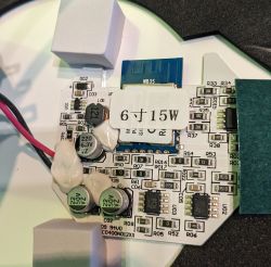
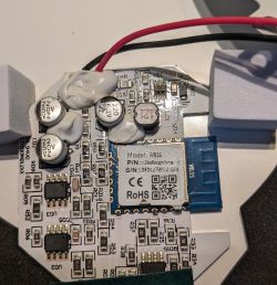
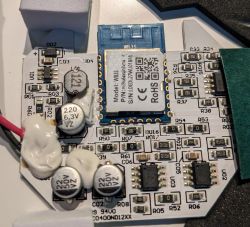
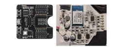
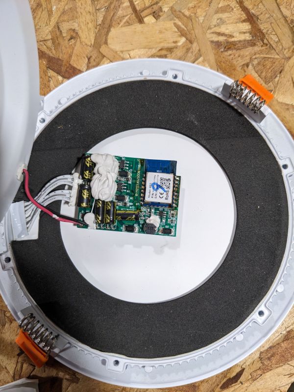
    I purchased these lights on Amazon. Teardown is simple, remove the 6 screws on the back of the downlight. The board is inside a white heat shrink. Cut along the edge with a razor so that you can simple slide the heat shrink back over the board after you're done.
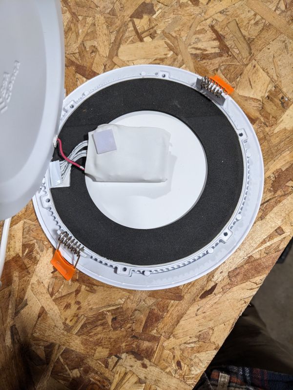
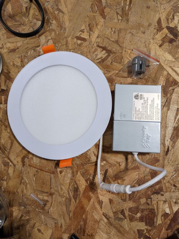
    CLOUDY BAY 6inch Smart Wifi LED Recessed Lights, RGBCW
    CLOUDY BAY 6inch Smart Wifi LED Recessed Lights, RGBCW

    I removed the WB3S module with a heat gun and stuck it in a DORHEA ESP8266 Code Burner to flash it. You may try flashing it while its installed but it wouldn't work for me with. Flashing while installed does work. My old serial programmer was malfunctioning. I successfully read and flashed it while installed using the DORHEA ESP8266 Code Burner.

    Pin configuration:

    P6: PWM/5
    P8: PWM/4
    P9: PWM/1
    P24: PWM/2
    P26: PWM/3

    After configuring the device and prompting the home assistant discovery, home assistant picked up the device and allowed me to control everything without any further configuration.

    The pictures here are of a light that had a catastrophic failure (I quickly assembled it for pictures here). I accidently shorted out a handful of pins on the back on a piece of metal, whoops.

    Edit: attached stock firmware.

    Cool? Ranking DIY
    About Author
    justinhunt1223
    Level 2  
    Offline 
    justinhunt1223 wrote 4 posts with rating 6. Been with us since 2023 year.
  • ADVERTISEMENT
  • #2 20372243
    p.kaczmarek2
    Moderator Smart Home
    Hello, would you be able to provide some more pictures of your device, how it looks like from outside and maybe inside, and if not, maybe some screenshots from the shop offer where it was bought?
    Helpful post? Buy me a coffee.
  • ADVERTISEMENT
  • #3 20372247
    justinhunt1223
    Level 2  
    Pictures uploaded, sorry!
  • #4 20372248
    p.kaczmarek2
    Moderator Smart Home
    No problem. I see you did well with the heatgun, although I think it would be also possible to flash it in place, you just need a reliable 3.3V power supply (not the cheapest one that is on the board of USB to UART converter).
    And of course, never attempt to flash anything connected to mains.

    Btw, it's good to see that Home Assistant Discovery is useful. Our team member @iprak did a very good job with that. It's all his work.
    Helpful post? Buy me a coffee.
  • #5 20372250
    justinhunt1223
    Level 2  
    p.kaczmarek2 wrote:
    ...although I think it would be also possible to flash it in place, you just need a reliable 3.3V power supply (not the cheapest one that is on the board of USB to UART converter).


    I have a handful more of these lights to flash and would love to not have to remove these to do it. I will attempt them in the next week and report back. I think my new USB -> serial on the way might work.
  • #6 20372252
    alfakenzo
    Level 9  
    Hi my friend, maybe oyu can provide a stock firmware dump from these device. And then could cloudcutter work on it.
  • #7 20372820
    p.kaczmarek2
    Moderator Smart Home
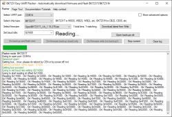
    Indeed, a factory flash backup can always be useful. That's why our new flash tool (still in Alpha stage) suggests to do automatic backup and then flash:
    https://github.com/openshwprojects/BK7231GUIFlashTool
    CLOUDY BAY 6inch Smart Wifi LED Recessed Lights, RGBCW

    Backups are always a good practice, not just when it comes to firmware.
    Helpful post? Buy me a coffee.
  • #8 20380068
    justinhunt1223
    Level 2  
    alfakenzo wrote:
    Hi my friend, maybe oyu can provide a stock firmware dump from these device. And then could cloudcutter work on it.


    I added the stock firmware to the original post, thanks for pointing that out. I don't have any experience with cloudcutter so I do not know.
  • ADVERTISEMENT
  • #10 20380173
    p.kaczmarek2
    Moderator Smart Home
    Don't worry, I'll forward it to them.
    Helpful post? Buy me a coffee.
  • #11 20380178
    alfakenzo
    Level 9  
    I don't mean the dump. I mean he should check the GitHub of Cloudcutter to flash it OTA and not to desolder all the spots. But the dump is necessary for the flash, when this firmware wasn't added by now.
  • #12 20415463
    amymariegerlach
    Level 5  
    EDIT - Neverminded, I think i found the directions on this site, they made a video and I am gonna give that a try.

    justinhunt1223

    Can you better explain the integration into Home Assistant?

    I flashed and successfully configured the light in the OpenBK web UI but don't know how to get it into Home Assistant.

    I searched device discovery and there is an old integration for that but it seems like it is no longer used or recommended.

    Thanks
  • #13 20415475
    p.kaczmarek2
    Moderator Smart Home
    Hello @amymariegerlach , maybe this tutorial can shed some light on HASS discovery?


    Helpful post? Buy me a coffee.
  • #14 20845418
    specialdude
    Level 9  
    Hi, I got 6 of those CloudyBay lights, and actually I was able only to connect to my wifi 1 out of 6, not sure what is going on. I have UniFi Dream Machine Pro,etc. I am Still troubleshooting. However a question... Can this custom firmware resolve my issue? Or is it basically the same firmware with some additions to just make it work with HA?
    Anyways would be nice to connect the lights to my HA too.
    I am new to flashing the modules part found in this post, but I wonder.... Without desoldering the module, how do you actually program it? How do you attach the hardware you mentioned to that light's module?

    Thanks for any info.
  • #15 20845550
    p.kaczmarek2
    Moderator Smart Home
    It is very hard to determine what is going on with your lights. If you are experiencing issue related to the range of the WiFI, then I am not sure if we can help much, because we just replace the firmware on the chip, we do not... well, replace the physical antena or the WiFi module itself. That being said, if your issue originates from the instability or bugs in Tuya firmware, then yes, we can help, we have different implementation of things, only the core SDK is the same that is available anywhere.

    You can give it a try, it's easy to restore device back to Tuya if you make 2MB backup. The process is not destructable.

    See our Youtube channel for some generic flashing step by step guides:
    https://www.youtube.com/@elektrodacom
    On the youtube channel above, we have videos step by step showing how to:
    - desolder WiFI module with cheap equipment
    - flash the WiFI module
    - solder WiFI module back in place
    - configure and start OBK
    For example, the video below is the flashing process for a ceiling light:


    @specialdude can you open one of your lights and tell me which WiFi module is inside? I can help you and guide you step by step.
    Helpful post? Buy me a coffee.
  • ADVERTISEMENT
  • #16 20846097
    specialdude
    Level 9  
    Hi,
    Thanks for replying.
    Definitely it is not a range of the wifi :) I literally tried to setup the light two feet away from the Access point (U6-LR) :) and the rest of the lights are in a line of sight from 6 to 16 feet.

    Here are two images:
    Close-up of a circuit board with electronic components and a 6V 15W label.

    Close-up of an electronic circuit with a WB3S module and several capacitors.


    Let me know if I can do anything with this one. What equipment do I need... etc.
    Definitely I am willing to experiment :)

    thanks!
  • #17 20846110
    p.kaczmarek2
    Moderator Smart Home
    That's good, it's WB3S.

    You may try following this tutorial:


    Here is our flasher tool:
    https://github.com/openshwprojects/BK7231GUIFlashTool
    First make 2MB flash backup, post it here, then flash OBK.

    You might also want to watch related videos on our channel, they may give you a better view how to flash this device.


    PS: Have you ever flashed Tasmota? The process here is similiar.
    Helpful post? Buy me a coffee.
  • #18 20846152
    specialdude
    Level 9  
    In addition to previous post :) ... I decided to do some research, haha...
    looks like it is this module: https://developer.tuya.com/en/docs/iot/wb3s-module-datasheet?id=K9dx20n6hz5n4

    Cleaned up a glue to confirm soldering points:
    WB3S electronic module with visible solder points on a PCB.

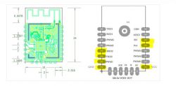
    So it looks like those:
    WB3S module diagram with highlighted soldering points.

    Added after 2 [minutes]:

    ohh and I have not noticed you already replied.... I will watch videos... I've not flashed Tasmota or etc... this is a new adventure :)
  • #19 20846182
    p.kaczmarek2
    Moderator Smart Home
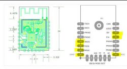
    PLEASE remember, this is a bottom view of modul:
    Diagram of an electronic module with pin labels on the right side.
    If you look from the top of the module, the TX1/RX1 is on the right.
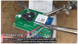
    See, here is a screenshot from our video:
    Soldering wires to an electronic module.
    On the screenshot, we solder RX and TX to the right side of the module (when looking from the top)
    Helpful post? Buy me a coffee.
  • #20 20846380
    specialdude
    Level 9  
    Hi,
    So here is where I get into uncharted territory...
    IF I get this device:
    https://www.amazon.com/DORHEA-Downloader-Comp...e-Transmission-Transceiver/dp/B08P37JQYX?th=1
    can it help me with my journey? What else do I need to simplify the whole process?

    The reason I ask cause, Like I see this little thing rigged in the video here :)
    CLOUDY BAY 6inch Smart Wifi LED Recessed Lights, RGBCW
    and I do not know much about playing like that so I wonder what I can use to make it simpler...
    like if I buy myself the DORHEA device... and I guess looks like I would need as well some usb to uart adapter... hmmm
    I can solder wires to the board but a clear and simplest procedure to make it connected to a PC to program it would very much help ... and like I said ... if I need to spend a few $ on it extra I guess I will for science :)
  • #21 20846406
    p.kaczmarek2
    Moderator Smart Home
    That thing may help.

    Alternatively, you may use NodeMCU or Arduino UNO or any other board like that, you just need to route out TX, RX, GND, 3.3V and futhermore, in case of those boards, you need to put the MCU (ESP or Atmega) in the RESET state, by shorting RESET to GND.
    Helpful post? Buy me a coffee.
  • #22 20846509
    specialdude
    Level 9  
    OK, so just not to complicate things.... or maybe I am :D Let's stick to this:
    https://www.amazon.com/DORHEA-Downloader-Comp...e-Transmission-Transceiver/dp/B08P37JQYX?th=1
    I can get that .
    and upon further reading I do not need any USB-UART device, it straight connects thru USB-A to MicroUSB cable to PC.

    Assuming I have it ... what is my next step to hook it all up?

    I think I would probably solder directly wires to it on a board like in one of the videos, but it looks like I need to do 4 of them....
    You told me about the two TX1/RX1 and any ideas about the other two?

    thanks
  • #23 20846514
    p.kaczmarek2
    Moderator Smart Home
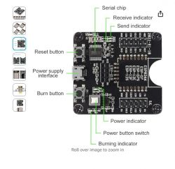
    The device you linked is in fact a fancy USB to UART converter, but it should be good:
    Converter module with labeled parts including serial chip and receive/send indicators.
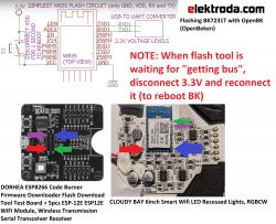
    Two other wires? Well, the answer is on linked video, but in general you need to connect:
    - GND to GND
    - 3.3V to 3.3V
    - RX to TX
    - TX to RX
    And then you do device reboot by disconnecting power when flasher is waiting for "getting bus".
    Helpful post? Buy me a coffee.
  • #24 20846561
    specialdude
    Level 9  
    can you visually on an attached below picture show how you would connect it?

    ESP8266 board on the left and WB3S module on a PCB on the right.


    Thank you up front very much!
  • #25 20846585
    p.kaczmarek2
    Moderator Smart Home
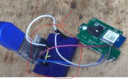
    Maybe something like that:
    Diagram and photos showing BK7231T flashing process with OpenBK.
    Keep in mind that in some cases you need to do more than that, see this video:
    https://www.youtube.com/watch?v=Yb3zXtBdSnE
    Sometimes you also need to swap RX with TX
    Helpful post? Buy me a coffee.
  • #26 20846653
    specialdude
    Level 9  
    Huhh... so that means I might have to as well to desolder one of those small CHIPs from RX/TX on the board? ouch uhhh hmmm fun. would be nice to know if I have to :)
    Cause if I have to do that, I start to think why not to just desolder the WB3S... I guess it would be much more difficult... than the other one.

    Is there an easy way to test if that chip removal will be needed in this scenario?
  • #27 20846677
    p.kaczmarek2
    Moderator Smart Home
    specialdude wrote:
    Huhh... so that means I might have to as well to desolder one of those small CHIPs from RX/TX on the board? ouch uhhh hmmm fun. would be nice to know if I have to :)

    The following happens only in few rare cases. I'd just give it a try first, then we will worry.

    Or maybe we could even check it now, but do you have a multimeter? The one that can check for continuity test and beep?

    Added after 1 [minutes]:

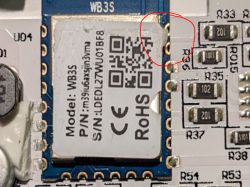
    You know what, I looked at the photo and I can clearly see that RX/TX is not used for anything on your device:
    Close-up of an electronic module on a circuit board with WB3S model inscription and various electronic components.
    This is good news, this means it will flash easily out of the box. There is no need to desolder stuff.
    Helpful post? Buy me a coffee.
  • #28 20846698
    specialdude
    Level 9  
    well, yes I do not see those solders at all :) "This is good news, this means it will flash easily out of the box. There is no need to desolder stuff."

    so then ... I just solder the other two wires and that is it? hmmm ?
  • #29 20846707
    p.kaczmarek2
    Moderator Smart Home
    Solder 4 wires, RX, TX, GND and 3.3V. You can look up our videos on how to solder
    Helpful post? Buy me a coffee.
  • #30 20846775
    specialdude
    Level 9  
    I solder things here and there ... so will be ordering the device above and will see how it goes :)

Topic summary

The discussion revolves around the teardown and flashing of Cloudy Bay 6-inch Smart Wifi LED Recessed Lights (model WB3S). Users share their experiences with disassembling the lights, flashing the firmware using a DORHEA ESP8266 Code Burner, and integrating the lights with Home Assistant. Key challenges include ensuring proper connections for flashing, troubleshooting WiFi connectivity issues, and the importance of using the correct baud rate and wiring configurations. Users also discuss the significance of avoiding 802.11b support in WiFi settings to enhance connectivity. Successful flashing and configuration steps are shared, along with recommendations for tools and techniques to simplify the process.
Summary generated by the language model.
ADVERTISEMENT