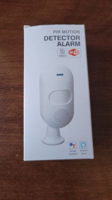
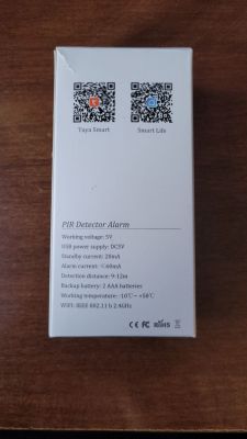
TuyaMCU is protocol used to communication between WiFi module and external MCU. Some Tuya devices are designed that way. It seems that your is without TuyaMCU.
Hmm if you are going to power is constantly, then indeed Deep sleep is not required. I that case configuration would be very, very simple.
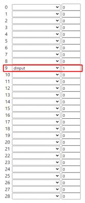
You just need to find out which GPIO is used dinput sensor.
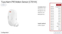
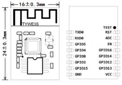
So, the device was using TYWE3S in the past? Here is GPIO13:
And here are CB3S GPIOs:
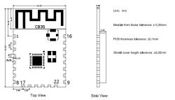
| Pin number | Symbol | I/O type | Function |
1 | RST | I | Low-level reset, high level active (the pin has been pulled high internally), correspond to CEN of the IC | 2 | ADC3 | AI | ADC pin, which corresponds to P23 of the IC | 3 | CEN | I | Enabling pin, which is pulled high internally to be compatible with other modules | 4 | P14 | I/O | A common GPIO interface, which corresponds to P14 of the IC | 5 | P26 | I/O | GPIOP_26, which corresponds to P26 of the IC, PWM 5 | 6 | P24 | I/O | GPIOP_24, which corresponds to P24 of the IC, PWM 4 | 7 | P6 | I/O | GPIOP_6, which corresponds to P6 of the IC, PWM 0 | 8 | VCC | P | Power supply pin (3.3V) | 9 | GND | P | Power supply reference ground | 10 | P9 | I/O | GPIOP_9, which corresponds to P9 of the IC, PWM 3 | 11 | TXD2 | I/O | UART2_TXD (used to display the module internal information), which corresponds to P0 of the IC | 12 | CSN | I/O | Production test control pin. If it is used as a common I/O pin, it must be connected to the VCC externally. Do not connect it to the ground before the module is powered on. | 13 | P8 | I/O | GPIOP_8, which corresponds to P8 of the IC, PWM 2 | 14 | P7 | I/O | GPIOP_7, which corresponds to P7 of the IC, PWM 1 | 15 | RXD1 | I/O | UART1_RXD (user serial interface), which corresponds to P10 of the IC. Do not connect it to the VCC. By default, the MCU serial port should be in low-level or high-impedance state. | 16 | TXD1 | I/O | UART1_TXD (user serial interface), which corresponds to P11 of the IC. Do not connect it to the VCC. By default, the MCU serial port should be in low-level or high-impedance state. | 17 | ADC3 | AI | (Not recommended. If needed, please use Pin 2) ADC port, which corresponds to P23 of the IC. Programmed SPI | 18 | P22 | I/O | (Not recommended ) GPIOP_22, which corresponds to P22 of the IC. Programmed SPI | 19 | CSN | I/O | The pull-up resistor is needed during usage of customers. Do not connect it to the ground before the module is powered on. Correspond to P21 of the IC. | 20 | P20 | I/O | (Not recommended. ) GPIOP_20, which corresponds to P20 of the IC. Programmed SPI |
I think we can already see which one is GPIO13 equivalent in CB3S. OpenBeken is using P* indexes.


