logo elektroda
logo elektroda
X
logo elektroda

[BK7231N/CBU] Door sensor without TuyaMCU - easy flashing and configuration guide

auntlydia 11244 51
ADVERTISEMENT
  • Helpful post
    #1 20683982
    auntlydia
    Level 10  
    Hi, first of all thank you for this amazing community and firmware, finally I got rid of Tuya apps thanks to OpenBK!
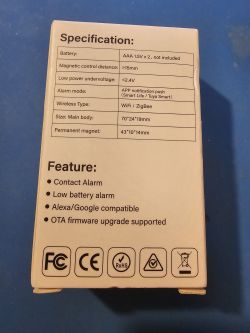
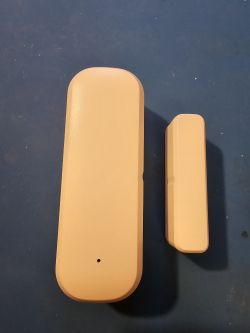
    I wanted to share my user experience on this device, since I successfully flashed and set up two of these recently, and they both worked exactly the same way. I believe it is the same device, no name Door Sensor (sold on AliExpress as AUBESS Door Sensor), also the one from this post: https://www.elektroda.com/rtvforum/topic3964392.html
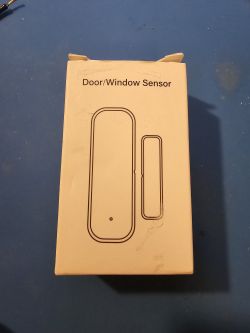
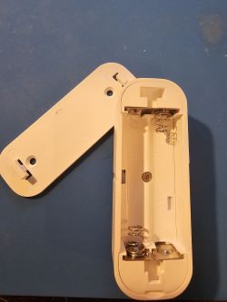
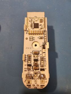
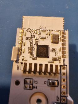
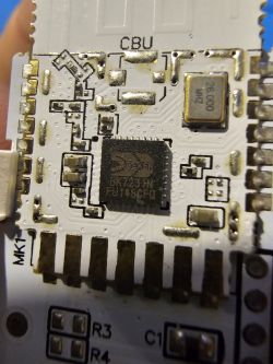
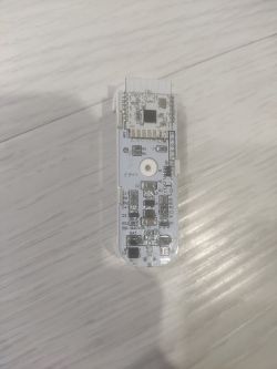
    A white cardboard box labeled Door/Window Sensor with a schematic outline of a door/window sensor set on a blue surface. Box of a door sensor with visible specifications and features printed on a light background. Opened white door sensor case with visible battery springs inside. Two white components of an AUBESS door sensor on a blue background. Door sensor PCB with electronic components and visible header pins for wire connection. Close-up of a PCB with exposed pins, a central microchip, and markings such as CBU and MK1, used in a door sensor. Close-up of a PCB with a BK7231N chip and visible pin labels.

    If you have trouble setting it up, maybe it helps to follow these steps.

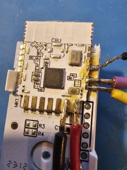
    1. prepare the Hardware and solder 5 wires to the pins, as in my picture:
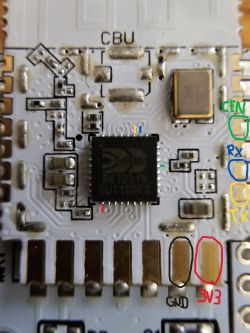
    Close-up of a PCB board with pin labels. Close-up of a door sensor circuit board with soldered wires.

    2. connect 4 wires (3.3V, GND, TX-->RX, RX-->TX) to UART-USB-Module and make sure to use 3.3V power setting on your module. be careful with double checking the wires correctly connected and make sure you don't get any shorts, don't put any batteries in the device and don't plug in the USB yet

    3. open Windows bk7231flasher software, select chip type BK7231N and then click "download latest from web"
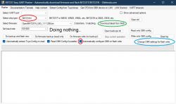
    Screenshot of BK7231 Easy UART Flasher application with highlighted options.
    4. this step is optional but I recommend it, since it makes everything easier. if you choose not to use this step, you will have to make all those settings via the web interface, which has the same result.
    click "change OBK settings for flash write", then fill in everything according to the screenshot. Important is to choose a different channel for the battery pins, or else the device will not work correctly. you can also predefine the flags, I chose flags 10, 11, 35 and 37, but maybe there are other settings that are useful too. Also, I chose to set a startup command [backlog dstime 30] to let the device sleep after 30 seconds from last sensor activity.
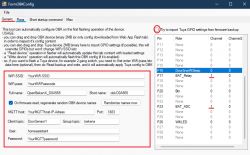
    Screenshot of OpenBK software configuration window.

    5. Now close the configuration window and connect the usb with everything attached as described above. it should pop up right away in UART port selection. double check all settings if you like. if you are happy with your settings, start the process with "Do backup and flash new", confirm the backup file name and look at the log field, it is now waiting for the device to power on.

    6. Now carefully take the wire that is connecet to CEN pin and quickly short it to the ground wire, only very short. The device should reset and the read/write process should start without any error messages. Then disconnect the device

    7. If everything went well, the device should connect to your wifi automatically after powering it on (you can either connect 3.3V from your USB or insert batteries). you might wanna push the device button every 30 seconds (or move a magnet next to it) to keep the connection alive, since it will sleep after 60 seconds or 30 seconds in my case. Now check the device IP address in your router and open the web interface through the address. double check the module, name, flag, mqtt, startup command configuration and lastly, start Home Assistant discovery, done!
    Information interface with BK7231N device and sensors data.

    I hope this might be useful to someone. Have fun!
  • ADVERTISEMENT
  • #2 20684016
    p.kaczmarek2
    Moderator Smart Home
    Very nice and detailed guide. I have split it into separate topic, as it really deserves to be seen.

    I am happy to see people making good use of "configure at flash time" feature that I've recently added to our flasher:
    https://github.com/openshwprojects/BK7231GUIFlashTool
    Good job!

    Btw, here's the previous door sensor topic:
    https://www.elektroda.com/rtvforum/topic3982902.html

    Regarding the guide itself - I will just give here some hints:
    - make sure to configure both sensor pin and button pin. Button pin can be used to emergency-wakeup device without moving door
    - if device does not wake up from one of the states (for example closing doors wakes it up, but opening doesn't), try entering DSEdge setting in short startup command or autoexec.bat, there are 3 possible options for that, see our docs
    A table excerpt from documentation describing the DSEdge parameter for DeepSleep mode.

    Our docs:
    https://github.com/openshwprojects/OpenBK7231T_App/blob/main/docs/commands.md
    Helpful post? Buy me a coffee.
  • ADVERTISEMENT
  • #3 20684082
    auntlydia
    Level 10  
    Thanks for bringing this forward - I must say I enjoyed a lot playing around with your software and it actually works great! I flashed temperature/humidity sensors and hidden switch relays as well - it all works flawlessly once the configuration is done properly.
    The option to preconfigure in the Windows flashing tool is very useful - especially for low power profile devices, as they seem troublesome to set up when we always have to find a workaround to reach the web interface during the short power-on intervals.

    Now I still have two questions:
    1. Is it possible for you to add the inverted DoorSnsrWSleep role to the list? In HA, there is always a way to invert buttons or actions, but the Door option is always the wrong way, so the status shows "Open" (which means On for the sensor) when the magnet is near the module, and "Closed" when the magnet is away. An inverted option in the module would solve this problem. I have tried the nPup and pd options but there is no difference. I realize in the other post this was already mentioned, however, I couldn't find the related setting in the current 7231N firmware.

    2. With all the low-powered modules, I am running into some problems. After some troubleshooting, I am certain that it has to do with the MQTT connection. Whenever the sensors quickly disconnect (sleep) after having sent updated data to the server, some other devices (some connected to MQTT, some not but also managed by HA integrations) in my home network lose the connection shortly and reconnect. With a number of sensors installed, this can get very annoying, since some other devices rely on a stable connection. The router itself should not be the problem. I want to further look into other forums about this problem, too, but maybe you have some idea about this, is this a typical issue?

    Thanks again, your work with this is very much appreciated!
  • #4 20684103
    p.kaczmarek2
    Moderator Smart Home
    There are multiple DoorSnsrWSleep types already and adding invert would require us to duplicate them all.

    What about a different approach: I can add a flag for you, flag saying "invert door sensor read state", which will work for all the door sensor types?

    It would be easier to maintain and document.

    Hmmm, that second issue seems very strange. I haven't seen anything like that before. The first thing I would suggest is to check if the problem persists without MQTT. Maybe... maybe your router doesn't like extra client connecting suddenly and then leaving?
    Helpful post? Buy me a coffee.
  • ADVERTISEMENT
  • #5 20684119
    auntlydia
    Level 10  

    Hi, thanks! Adding such a flag would be a great idea! I will test it once it's possible and give you feedback if it works.

    As for the other issue, it could be quite complex. I found a thread that describes a similar problem: https://community.home-assistant.io/t/constant-mqtt-devices-disconnections-socket-error/83477

    and it mainly concerns Tasmota devices and a Tapo camera. Both of these devices disconnect and reconnect to HA once one of the door or temperature/humidity sensors close their connection. The router seems not to be the problem because the devices don't lose their WiFi connection but the connection/availability to Home Assistant. It has to be something with MQTT or another Home Assistant integration. I will dig into that further because I need to fix this problem or else my smart home doesn't work properly. But it is another topic. Maybe keep this topic here to the door sensor setup, and I can open another topic once I have more information on it.
  • #7 20691114
    auntlydia
    Level 10  

    Thanks! As of the newly updated version 1.17.212, it is possible to invert sensor status with flag 42. It works, and the HA workaround is no longer necessary. Very nice!

    As for my other problem I mentioned before, it turned out to be a router problem, so there was nothing wrong with the sensors, firmware, MQTT, or Home Assistant. All good. Thanks again!
  • #8 20691486
    simovicsava
    Level 7  

    Thanks! With flag 42, it works great and the HA workaround is no longer necessary!
  • ADVERTISEMENT
  • #9 20715097
    woszu
    Level 15  
    Hello
    I have a similar sensor, but a little differently organized hardware-wise (different BK pins). I've already arrived at what and how and it works nicely, but.....
    I wanted to use the sensor to report the opening of a letterbox. Unfortunately, the mailman opens the box for too short a time for the sensor to report anything. After a deep sleep, it needs some time to connect. Is there any way to set a flag that there was a change in input state after waking up and before connecting?
  • #10 20715121
    p.kaczmarek2
    Moderator Smart Home
    From what I remember, the latest version of the DoorSensor driver (the one that's on Github) keeps an eye on the situation where "the door was opened and closed before the sensor connected to WiFi" and even then it should report the status correctly. We tested this with colleague @nihildiximus .
    Screenshot of text regarding the DoorSensor driver.
    Do you use the DoorSensor driver, or did you configure the whole thing manually, with a script?
    Helpful post? Buy me a coffee.
  • #11 20715240
    woszu
    Level 15  
    I am using DoorSensor. The problem is that moving the magnet away (changing the input to OFF) wakes up the BK, but after a while reapplying the magnet changes back to ON before the device connects to the HA, and when it does, it reports the ON state (which is the current state), and I want to report this temporary OFF
  • #12 20718232
    auntlydia
    Level 10  

    Hi, based on the previous answer, this problem should be solved with the reporting of temporary states between WiFi connections..!? Have you updated to the latest OpenBK?

    Also, I thought about a similar idea: to have a notification once a post has been inserted into my mailbox. Since my mailbox is not to be opened by anyone else than myself, the post is just inserted into it through a slot. How about installing a wireless motion sensor into the mailbox? It would report motion triggered by an inserted letter or packages.

    Another idea: do you have the option to supply permanent wired power to the sensor? Then you would not need to set the sensor to Sleep-state, but could use a normal input with instant recognition and permanent WiFi connection.
  • #13 20718299
    p.kaczmarek2
    Moderator Smart Home
    I am confused because I am sure that we've fixed that issue with @nihildiximus and that the door sensor indeed reports the state from before it connected to MQTT.

    See:
    C code snippet about publishing initial door sensor states using MQTT.
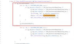
    After getting WiFi and MQTT, for the first 3 loops (first 3 seconds), it force-publishes the initial states of pins which is queried in new_pins.c ...
    C code snippet setting GPIO pin roles Code snippet in C programming language with highlighted variable bSampleInitialState.
    Maybe I need to check it myself, find some sensor...


    @woszu - what about just reporting a custom value on every reboot? Doing a publish command or a SendGET in autoexec.bat?
    Helpful post? Buy me a coffee.
  • #14 20721162
    woszu
    Level 15  

    And yet it works.
    I fired up MQTT Explorer and it does indeed report a 1 for 3s and then goes back to zero.
    Sorry for the confusion, I checked on the BK settings page and didn't see it there :) .
  • #15 20721184
    p.kaczmarek2
    Moderator Smart Home
    Thanks for the info, as I was already wondering how it could have broken down since the last tests. And in that case it's good to hear that it continues to work.

    If you have problems you can always manually do from autoexec.bat MQTT publish or HTTP GET.

    If you have any other questions or need some functionality, go ahead and write.
    Helpful post? Buy me a coffee.
  • #16 20835517
    emrecetinkaya86
    Level 4  

    Hi all,

    First of all, thank you all for sharing information here. It is very much appreciated!

    I have the same device and successfully burned the firmware on it. I applied the template and tried all the pin configurations described here, but no matter what I do, I get the following result:
    - On the index page, the sensor value doesn't change no matter what I do (changing magnet positions).
    - In HA, the sensor sends a "turned on/turned off" message every 10 seconds while it's powered on, by itself, without any change with the magnet.

    It seems like the pin number 16 may be wrong, or what am I missing?

    Thanks
  • #17 20835677
    p.kaczmarek2
    Moderator Smart Home
    Maybe they changed something., Try to extract the template (but disable door sensor driver for that time):
    https://www.youtube.com/watch?v=WunlqIMAdgw
    Helpful post? Buy me a coffee.
  • #18 20836473
    emrecetinkaya86
    Level 4  

    Hi,

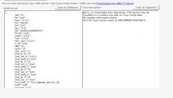
    Thanks for the answer. I've just tried but from binary, it says no meaningful data:

    Screenshot showing meaningless JSON data on the left and an error message on the right.

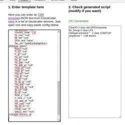
    And when I paste JSON in web app:

    Screenshot of a web application with a JSON converter in OpenBeken.

    I'm stuck... This is my first time with OpenBeken and I don't want to give up...
  • #19 20837792
    emrecetinkaya86
    Level 4  

    >>20835677

    Hi @p.kaczmarek2 and all,

    Yes they changed something, which is the pin number of hall effect sensor. At first I'm happy that I'll contribute to the community with this experience for the first time, with my pleasure! What to do to add this change what I explained below to the templates?

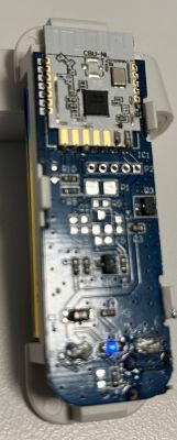
    After looking twice, I've recognized that the module on the device is CBU-NL instead of CBU. This is how the module looks like:

    Close-up of the CBU-NL electronic module with visible connectors and components on the circuit board.

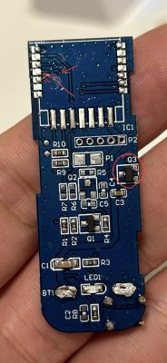
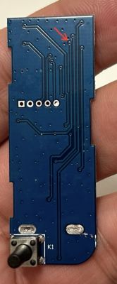
    Also, the board is different than the one in this topic and others in the forum. I've traced the hall effect sensor pin from it to module pin and it corresponds to pin 22, instead of 16! And it's pulled down.

    Image of a printed circuit board (PCB) held in hand with marked components. Photo of a circuit board with a marked pin.

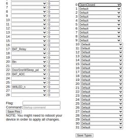
    Then I've changed my pin configuration (other pins are still the same, only the hall effect sensor pin number has been changed):

    Screenshot of pin configuration for a module with channel type settings.

    I've also changed the channel type of channel 0 which hall sensor pin included to "openclosed", so I can see on the index page the status more clearly.

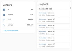
    The only thing remaining now is, when the module is awake after pin change, it sends sensor turned on/off messages every 10 seconds and without any change. And the sensor value came automatically doesn't show the correct value, I've copied sensor yaml lines from OpenBeken web to configuration yaml in HA and it shows the correct value.

    Screenshot of a user interface displaying sensor information and an event log.

    And my last question is, when the module wakes up, it stays awake for at least a minute and then sleeps. Is there any way to set it up like "do your job and sleep"? Sorry again if I ask something which was explained before, as I'm a newbie.

    Enjoy
  • #20 20837805
    p.kaczmarek2
    Moderator Smart Home
    Thanks for the info. Can you include template from the Web App so I can add it to devices list?

    I think you can set a DSTime variable to adjust the time how long it's up.

    Regarding on and off messages, is the status read in the OBK panel correct?

    PS: I think you can change channel name from that "1" string to any other with setChannelLabel command
    Helpful post? Buy me a coffee.
  • #21 20837864
    emrecetinkaya86
    Level 4  
    Hi @p.kaczmarek2,

    Here is the template:

    Code: JSON
    Log in, to see the code


    And this is the link to the product: https://www.aliexpress.com/item/1005005216868...der_detail.order_detail_item.3.63b443cepjkRkP

    Thanks, I've changed the DSTime value to 15 seconds, as it's more than enough to send MQTT data.

    Quote:
    Regarding on and off messages, is the status read in the OBK panel correct?


    I really don't have an idea about the answer... After I made MQTT configuration on the OBK web, I triggered discovery and those values showed up. And the value of "1" sensor doesn't change, as I said I manually added the sensor (which works very well) with this configuration to the YAML file of HA:

    mqtt:
      binary_sensor:
        - unique_id: "doorsensormain_binary_sensor_0"
          name: "Maindoor"
          state_topic: "doorsensor/0/get"
          qos: 1
          payload_on: 1
          payload_off: 0
          availability:
            - topic: "doorsensor/connected"


    Quote:
    PS: I think you can change the channel name from that "1" string to any other with the setChannelLabel command


    It's very useful information, thanks! I'll change it as soon as I make it work when the sensor value changes.

    Thanks!
  • #22 20881128
    Xinayder
    Level 8  
    I have a very similar sensor I bought from AliExpress, branded as AUBESS: https://www.aliexpress.com/item/1005004699337230.html

    I used the Windows flasher tool and it worked perfectly, it even loaded the configuration retrieved from the original firmware.

    I also checked the door sensor guide on the forums and had to do a quick tweak on my sensor. By default, the battery relay/adc were set to the same channel as the door sensor, so whenever the HAL sensor was triggered, it would go to the opposite state because of the relay. To fix this, I set the battery ADC and relay to a different channel.

    The HAL sensor pin was set to DoorSnsrWSleep (no pull down or pull up), as instructed in the guide: https://www.elektroda.com/rtvforum/topic3960149.html

    I also enabled the quick wifi connect flag to prevent waiting a long time to broadcast the values. This is my template:

    {
      "vendor": "Tuya",
      "bDetailed": "0",
      "name": "AUBESS Smart Wifi Door/Window Sensor (no TuyaMCU)",
      "model": "enter short model name here",
      "chip": "BK7231N",
      "board": "TODO",
      "flags": "1152",
      "keywords": [
        "TODO",
        "TODO",
        "TODO"
      ],
      "pins": {
        "16": "DoorSnsrWSleep;0",
        "17": "BAT_Relay;2",
        "20": "Btn;1",
        "23": "BAT_ADC;2",
        "26": "WifiLED_n;0"
      },
      "command": "",
      "image": "https://obrazki.elektroda.pl/YOUR_IMAGE.jpg",
      "wiki": "https://www.elektroda.com/rtvforum/topic_YOUR_TOPIC.html"
    }


    EDIT: I've also attached the original firmware extracted from the sensor.
  • Helpful post
    #23 20896836
    spln
    Level 5  

    >>20837792

    I also got a similar sensor, the PCB looks the same, but with different pin configuration so created a separate topic for it:
    [BK7231N CBU-NL] ONENUO Tuya Wifi Door Sensor - 19JWT

    The HAL sensor has neither pull-up nor pull-down, battery is read through a switchable voltage divider like above.
  • #24 20942554
    pincopallino1010
    Level 5  

    >>20683982
    Hi, @auntlydia @pkaczmarek262! I have 9 of these devices and am preparing to modify them. Once you follow this guide do you need to set/do anything else from the web interface? Is there anything to tweak/install to better manage the battery consumption of the devices?
    Also, how can I do to send a request to a webserver as soon as a port opening is detected? :)
  • #25 20947444
    pincopallino1010
    Level 5  

    Nvm I was able to flash them without any problems! Thanks a lot for the guide :)
    Just a couple of questions @auntlydia @pkaczmarek262 (sorry for the tag), is there anything to tweak/install to better manage the battery consumption of the devices? Is it possible to totally disable MQTT since I do not use it?
    Also, how can I do to send a request to a webserver as soon as a door open/close is detected? :)
    Thank you in advance!
  • #26 20968460
    pincopallino1010
    Level 5  

    >>20683982

    Hi @auntlydia @p.kaczmarek2 (Sorry for the tag again). I flashed the firmware on one of these devices by following this guide (without entering any configuration via the tool) and unfortunately I can't figure out why the device seems to be "not working."
    It boots but whatever configuration I enter (pin, flag, wifi...) this is not maintained and also the web application page does not load.
    Screenshot of a web browser showing a blank page at the address 192.168.4.1.
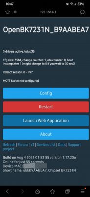
    The screen I end up in when I connect to the device is as follows (photo).
    Screenshot of the OpenBK7231N device web interface showing configuration options.
    Even if I enter the configurations through the tool nothing seems to change, plus the led doesn't seem to light up anymore...
    Can anyone help me? Thanks!
  • #27 20968463
    divadiow
    Level 34  
    I'd start by flashing an up-to-date version of OBK. The one in the screenshot is from August.
  • #28 20968641
    p.kaczmarek2
    Moderator Smart Home
    Wait, do I understand correctly, you haven't configured it? I can see no drivers running, nothing is set... you need to configure it first, I guess.
    Helpful post? Buy me a coffee.
  • #29 20969015
    pincopallino1010
    Level 5  

    @divadiow I had already tried to install the latest version but it gave me the same problems, so I tried to install the one that is used in the guide

    @p.kaczmarek2 Initially I followed the procedure from top to bottom (entering the configurations via the tool) but I was having the same problems, so I thought of entering them "by hand" after flashing the firmware but nothing... for example if I set the wifi network to connect to it doesn't work when rebooting and it keeps creating its wifi to connect. Same with the pins, every time I reboot the device all the fields reset.

    What does it mean: "0 drivers active, total 35"
    And: "boot incompletes 1 (might change to 0 If you wait to 30 sec)!"

    Maybe they are the problem but I really don't understand what is going wrong....
  • #30 20983574
    insmod
    Level 25  

    Circuit board with visible electronic components.
    Hardware mod, U2 is CHT8305. Now waiting for simultaneous pin and timer deep sleep support
    P7->CHT8305_SCK
    P8->CHT8305_SDA

Topic summary

The discussion centers on flashing and configuring BK7231N-based door sensors without TuyaMCU, specifically devices sold as AUBESS Door Sensor and similar models with CBU or CBU-NL boards. Users share detailed guides on flashing using OpenBK firmware and the BK7231GUIFlashTool, including pin configurations for hall effect sensors, battery ADC, button inputs, and WiFi LED control. Key issues addressed include inverting door sensor logic states (solved by adding flag 42 in firmware version 1.17.212), handling short door open events (e.g., letterbox openings) with deep sleep and MQTT reporting, and managing battery consumption via PowerSave commands. Some users report hardware variations requiring different pin assignments, such as hall sensor pins on GPIO22 instead of GPIO16. Problems with device booting after flashing, flash write errors, and recovery methods including full 2MB flash backups are discussed. The door sensor driver relies on MQTT for state reporting and sleep management; disabling MQTT is possible but not recommended due to battery drain. Alternatives using HTTP requests via autoexec.bat scripts are considered. Hardware modifications like enabling step-up converters and integrating additional sensors (e.g., CHT8305 temperature/humidity) are also mentioned. The community provides templates for device configuration and troubleshooting advice for flashing and firmware stability.
Summary generated by the language model.
ADVERTISEMENT