Good afternoon. I wanted to share with you the experience of firmware wi fi extension cable IMPITER WiFi Smart Power Strip.
![[BK7231T/WB3] Experience: Firmware for IMPITER WiFi Smart Power Strip - Inside Look & Setup [BK7231T/WB3] Experience: Firmware for IMPITER WiFi Smart Power Strip - Inside Look & Setup](https://obrazki.elektroda.pl/9881821800_1679809090_thumb.jpg)
This is how it looks inside:
![[BK7231T/WB3] Experience: Firmware for IMPITER WiFi Smart Power Strip - Inside Look & Setup [BK7231T/WB3] Experience: Firmware for IMPITER WiFi Smart Power Strip - Inside Look & Setup](https://obrazki.elektroda.pl/7305388200_1679810204_thumb.jpg)
The extension cord is assembled on the basis of a chip BK7231T / WB3
![[BK7231T/WB3] Experience: Firmware for IMPITER WiFi Smart Power Strip - Inside Look & Setup [BK7231T/WB3] Experience: Firmware for IMPITER WiFi Smart Power Strip - Inside Look & Setup](https://obrazki.elektroda.pl/7163841500_1679809142_thumb.jpg)
![[BK7231T/WB3] Experience: Firmware for IMPITER WiFi Smart Power Strip - Inside Look & Setup [BK7231T/WB3] Experience: Firmware for IMPITER WiFi Smart Power Strip - Inside Look & Setup](https://obrazki.elektroda.pl/2768678900_1679809171_thumb.jpg)
On the chip itself, the pinout is as follows
![[BK7231T/WB3] Experience: Firmware for IMPITER WiFi Smart Power Strip - Inside Look & Setup [BK7231T/WB3] Experience: Firmware for IMPITER WiFi Smart Power Strip - Inside Look & Setup](https://obrazki.elektroda.pl/5253581500_1679810083_thumb.jpg)
![[BK7231T/WB3] Experience: Firmware for IMPITER WiFi Smart Power Strip - Inside Look & Setup [BK7231T/WB3] Experience: Firmware for IMPITER WiFi Smart Power Strip - Inside Look & Setup](https://obrazki.elektroda.pl/4592433800_1679810090_thumb.jpg)
In order not to solder the chip, here is an example of where to solder on the board
![[BK7231T/WB3] Experience: Firmware for IMPITER WiFi Smart Power Strip - Inside Look & Setup [BK7231T/WB3] Experience: Firmware for IMPITER WiFi Smart Power Strip - Inside Look & Setup](https://obrazki.elektroda.pl/3182756500_1679810287_thumb.jpg)
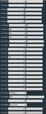
This is how you need to set up channels
![[BK7231T/WB3] Experience: Firmware for IMPITER WiFi Smart Power Strip - Inside Look & Setup [BK7231T/WB3] Experience: Firmware for IMPITER WiFi Smart Power Strip - Inside Look & Setup](https://obrazki.elektroda.pl/2705300800_1679810476_thumb.jpg)
Here is the json config:
{
  "vendor": "Tuya",
  "bDetailed": "0",
  "name": "WiFi Smart Power Strip",
  "model": "IMPITER",
  "chip": "BK7231T",
  "board": "WB3",
  "flags": "1024",
  "keywords": [
    "Mains Power Strip",
    "USB Power Supply",
    "4 Gang"
  ],
  "pins": {
    "1": "WifiLED_n;0",
    "6": "Rel;1",
    "7": "Rel;4",
    "8": "Btn_Tgl_All;0",
    "9": "Rel;3",
    "24": "Rel;2",
    "26": "Rel;5"
  },
  "command": "",
  "image": "https://obrazki.elektroda.pl/9881821800_1679809090_thumb.jpg",
  "wiki": "https://www.elektroda.com/rtvforum/topic3967318.html"
}


