logo elektroda
logo elektroda
X
logo elektroda

Discovering Pin-to-Channel Connections for PWM on Calex E27 LED Bulbs with BK7231T Chip

nielspiersma 1179 10
ADVERTISEMENT
  • #1 20565581
    nielspiersma
    Level 9  
    Hi,
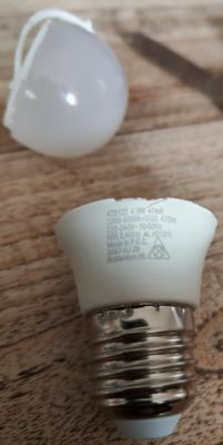
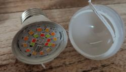
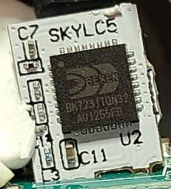
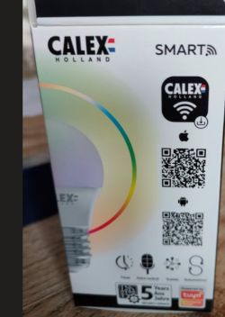
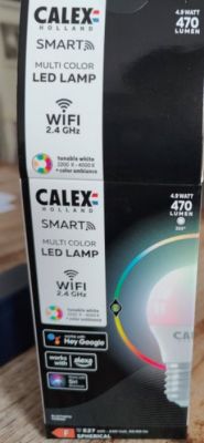
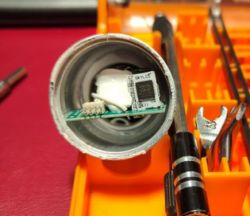
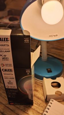
    I was working on a new breakdown of 10 Calex E27 light bulbs I got on ibood.com. I successfully dismantled one of the bulbs and found a BK7231T inside. Already flashed it with cloudcutter and now I am stuck. Discovering Pin-to-Channel Connections for PWM on Calex E27 LED Bulbs with BK7231T Chip Discovering Pin-to-Channel Connections for PWM on Calex E27 LED Bulbs with BK7231T Chip Discovering Pin-to-Channel Connections for PWM on Calex E27 LED Bulbs with BK7231T Chip Discovering Pin-to-Channel Connections for PWM on Calex E27 LED Bulbs with BK7231T Chip Discovering Pin-to-Channel Connections for PWM on Calex E27 LED Bulbs with BK7231T Chip Discovering Pin-to-Channel Connections for PWM on Calex E27 LED Bulbs with BK7231T Chip Discovering Pin-to-Channel Connections for PWM on Calex E27 LED Bulbs with BK7231T Chip Discovering Pin-to-Channel Connections for PWM on Calex E27 LED Bulbs with BK7231T Chip Discovering Pin-to-Channel Connections for PWM on Calex E27 LED Bulbs with BK7231T Chip Discovering Pin-to-Channel Connections for PWM on Calex E27 LED Bulbs with BK7231T Chip
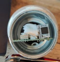

    I cannot find the correct PWM settings for the pins. Any tips on how I can determine with Pin goes to which channel...

    Thanks
    NIels

    Added after 4 [minutes]:

    After flashing the bulb is on, connected to the wifi and I am able to connect to the web interface.
    However, after setting the PWM and pressing toggle once, the light goes off but I am not able to power the light on again.

    Would incorrectly assigning the PWM potentially damage the leds? The web page keeps working fine though.

    Niels

    Added after 42 [minutes]:

    Okay,
    The Skylc5 module only has 3 usable GPIO pins; GPIO04, GPIO12 and GPIO14.
    So I can't set 5 PWM's. Having said that, how can I map GPIO to P(n) :)?
    NIels

    Added after 29 [minutes]:

    Well I did some research and figured that GPIO12 points to PWM4, GPIO14 to PWM5 and GPIO4 to PWM1.

    Configured them, but no luck, nothing lights.

    Are you allowed to configure only one PWM, at least to figure out the correct pin? Or are all PWM's mandatory?

    NIels
  • ADVERTISEMENT
  • #2 20565883
    p.kaczmarek2
    Moderator Smart Home
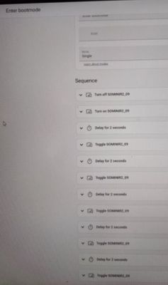
    Hello, if it's really a PWM-based bulb (no SM2135, etc), then you can even set GPIO roles to RELAY and just toggle relays to see if it works.

    You can also set PWM roles and enable "Show raw PWMs" in flags.

    But wait...

    Only 3 useable GPIO and RGBCW bulb?

    That must be SM2135 or similar.
    Discovering Pin-to-Channel Connections for PWM on Calex E27 LED Bulbs with BK7231T Chip
    It must be either SM2135, or BP5758, or BP1658C, etc...

    Please investigate the board and check the IC markings.
    Helpful post? Buy me a coffee.
  • #3 20566096
    nielspiersma
    Level 9  
    I'll do some further investigation. On the LED plate itself is no IC, so it must be somewhere on the PCB.
    I will need to scrape off a lot of glue to find any IC. But at least I know what I am looking for now.
    Once found will share and create a proper tear down :)
    Niels
  • ADVERTISEMENT
  • #4 20566145
    p.kaczmarek2
    Moderator Smart Home
    If you have a binary dump from this device, you can also use a cloudcutter profile to generate OBK config. Of course, it must be a cloudcutter profile of the same device model you have.


    Helpful post? Buy me a coffee.
  • ADVERTISEMENT
  • #5 20566615
    nielspiersma
    Level 9  
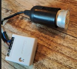
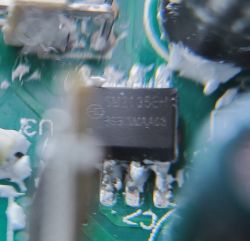
    Well found it. covered under a lot of putty as sm2135. Now I'll trace the pons back to the skylc5 and see if I can get it to work.. [img-0] Discovering Pin-to-Channel Connections for PWM on Calex E27 LED Bulbs with BK7231T Chip
  • #6 20566663
    p.kaczmarek2
    Moderator Smart Home
    Good job, it should be very easy to get it running now. Even while guessing, there aren't many possible combinations with SKYLC5 module which has few available GPIOs.
    Helpful post? Buy me a coffee.
  • #7 20566704
    nielspiersma
    Level 9  
    I agree; there are not many combos, but I am unsure of the mapping of the P-numbers.
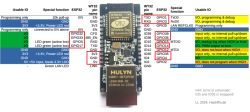
    When looking at the pin out of the TYLC5 (likely a very close clone) https://developer.tuya.com/en/docs/iot/wifilc5module?id=K9605t3bpxf75
    I figured

    CLK -> GPIO14 = P6
    DAT -> GPIO12 = P7

    No luck tried flipping P6/P7 still no joy. Now trying all combos..
    But with 5 PWM's that is still a lot of combo's (625)...
    Ant a chance we can figure it out easier?

    Niels

    Added after 25 [minutes]:

    Okay,

    I pulled out the magnifier, and based on https://jilles.com/img/tuya/SKYLC5-1.PNG I concluded that GPIO4 (right bottom finger) goes to the bottom pin on the right on the square beken chip. The only matching PWM is, based on https://obrazki.elektroda.pl/6366133600_1673944535.png , P25 PWM3.

    When following GPIO12 and GPIO14 they connect to P23 and P24 (PWM1 and PWM2). As those are the only ones used I configured PWM1 for CLK and PWM2 for DAT, nothing happened (also not after reboot). I flipped the configure, so PWM1 for DAT and PWM2 for CLK, no joy...

    I need to think this over, unless someone has a clue they want to share.

    Niels

    Added after 1 [hours] 31 [minutes]:

    Nailed it!
    I had to use PWM4 / P24 for SM2135DAT and PWM5 / P26 for SM2135CLK.

    Need to play with the color map but it works.

    Will now flash the remaining 8 bulbs!

    Discovering Pin-to-Channel Connections for PWM on Calex E27 LED Bulbs with BK7231T Chip


    Niels
  • #8 20567164
    p.kaczmarek2
    Moderator Smart Home
    That's quite a common choice of GPIO for SM2135:
    Discovering Pin-to-Channel Connections for PWM on Calex E27 LED Bulbs with BK7231T Chip
    Helpful post? Buy me a coffee.
  • #9 20567211
    nielspiersma
    Level 9  
    I think I am almost there, and I can't figure out the SM2135_MAPS setting. However, I did the following, and maybe someone can help me with the correct MAPS setting:
    When entering the color codes for RGB I get the following results
    color #00FF00 -> Green -> blue
    color #0000ff -> Blue -> red
    color #ff0000 -> Red -> white

    Clearly messed up, but how to apply the MAPS command so Green becomes Green, Blue becomes Blue and Red becomes Red.

    Thanks
    NIels
  • ADVERTISEMENT
  • #10 20567222
    p.kaczmarek2
    Moderator Smart Home
    Start with map 0 1 2 3 4 and then, for example, if green is swapped with red, swap first and third number.

    You can also use the LED_Map tool in Web App -> Tools
    Helpful post? Buy me a coffee.

Topic summary

The discussion revolves around the exploration of PWM (Pulse Width Modulation) pin-to-channel connections in Calex E27 LED bulbs equipped with the BK7231T chip. After successfully dismantling a bulb and flashing it with CloudCutter, the user encountered difficulties in identifying the correct PWM settings for the pins. Participants suggested checking for specific ICs like SM2135, BP5758, or BP1658C on the PCB, which led to further investigation. The user eventually identified the SM2135 chip and traced the GPIO connections, attempting various configurations for PWM channels. The final solution involved adjusting the MAPS settings to correctly map color codes for RGB outputs. A teardown of the bulb is planned for sharing with the community.
Summary generated by the language model.
ADVERTISEMENT