logo elektroda
logo elektroda
X
logo elektroda

[CBU/BK7231N and SH4/CMTOV30] Wi-Fi IR+RF Remote Control (S11)

JustAnotherUser 5592 24
ADVERTISEMENT
  • #1 20566501
    JustAnotherUser
    Level 2  

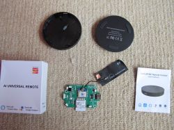
    Pictures:
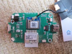
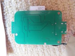
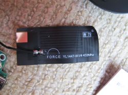
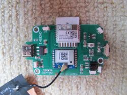
    [CBU/BK7231N and SH4/CMTOV30] Wi-Fi IR+RF Remote Control (S11) [CBU/BK7231N and SH4/CMTOV30] Wi-Fi IR+RF Remote Control (S11)

    [CBU/BK7231N and SH4/CMTOV30] Wi-Fi IR+RF Remote Control (S11)

    [CBU/BK7231N and SH4/CMTOV30] Wi-Fi IR+RF Remote Control (S11)[CBU/BK7231N and SH4/CMTOV30] Wi-Fi IR+RF Remote Control (S11)

    [CBU/BK7231N and SH4/CMTOV30] Wi-Fi IR+RF Remote Control (S11) [CBU/BK7231N and SH4/CMTOV30] Wi-Fi IR+RF Remote Control (S11)

    Purchased on Amazon https://www.amazon.com/dp/B0BY2C68BJ
    [CBU/BK7231N and SH4/CMTOV30] Wi-Fi IR+RF Remote Control (S11)
    [CBU/BK7231N and SH4/CMTOV30] Wi-Fi IR+RF Remote Control (S11) [CBU/BK7231N and SH4/CMTOV30] Wi-Fi IR+RF Remote Control (S11)


    Pinout:
    CBU PinBK7231NFunctionBoard TP
    1P14 (SPI_SCK)SH4 CLKSCK
    2P16 (SPI_MOSI)SH4 SDIO via R9
    3P20SH4 GPIO1INT1
    4P22SH4 GPIO2INT2
    5ADCButton via RC networkADC
    6RX2
    7TX2
    8P8IR receiver
    9P7IR tx
    10P6
    11P26
    12P24
    13GNDGNDGND
    143V33V33V3
    15TX1TXD
    16RX1RXD
    17P28
    18CENCEN
    19P9Status LED
    20P17 (SPI_MISO)SH4 SDIO via (not populated) R18
    21P15 (SPI_CS)CSN

    The button is connected to ADC via a RC network:
    [CBU/BK7231N and SH4/CMTOV30] Wi-Fi IR+RF Remote Control (S11)


    As the IR section is identical to the well-covered S08 at https://www.elektroda.com/rtvforum/topic3920360.html I'm mainly focusing on the RF section.

    According to https://developer.tuya.com/en/docs/iot/sh4-module-datasheet?id=Ka04qyuydvubw the SH4 module is based around a CMTOV30-EQR chip. While I was not able to find information on this chip, CMOSTEK's CMT2300 has a suspiciously similar part number (CMT2300A-EQR) and the same pinout. Looking at the SPI traffic it looks like the register map is the same as well.

    The SH4 is connected to the CBU via 2 interrupt lines, 2 chip select lines, a clock line, and a bi-directional data line. Although the datasheet for the CMT chip says it can do SPI at 5 MHz, the CMU is only moving data at approximately 500 kHz. Looking at it with a logic analyzer it looks like they might be bit-banging the data instead of using the hardware SPI peripheral as the frequency changes slightly between sending and receiving:
    [CBU/BK7231N and SH4/CMTOV30] Wi-Fi IR+RF Remote Control (S11)

    SPI traffic on boot: sh4-boot..b.csv Download (1.64 kB)

    That's about as far as I've gotten so far. It looks like using this RF chip involves a whole lot of copying and pasting.
  • ADVERTISEMENT
  • #2 20567155
    p.kaczmarek2
    Moderator Smart Home
    Very interesting, so they are using a SPI protocol to communicate with RF module? Do you have any idea what kind of protocol are they using, is it documented somewhere, or do we have to capture all their data and reverse engineer the protocol ourselves?
    Helpful post? Buy me a coffee.
  • ADVERTISEMENT
  • #3 20567166
    JustAnotherUser
    Level 2  
    It's SPI, but it uses a bi-directional data line so the master needs to write the register address out on it and then change it to an input to read the response. It's described in the CMT2300A datasheet http://www.cmostek.com/download/CMT2300A-EN-Rev0.7.pdf page 27, and the register table is on page 40. Basically the CSB line goes low, the master writes 7 address bits plus the read/!write bit, and then either reads or writes 8 bits of data before setting CSB high again.
  • #4 20595851
    codyroseman
    Level 2  
    Does anyone have a dump of the original firmware? I've flashed OpenBeken and since the rf module isn't supported I'd like to return it to stock. Thanks
  • ADVERTISEMENT
  • #5 20595876
    JustAnotherUser
    Level 2  
    Unfortunately unless you have a backup of that specific module you're not going to be able to completely get it back to stock as each module has a serial number and key burned in. The best you'll get is local-only control with TinyTuya or HA. There's a stock firmware image posted lower down in the discussion over at https://github.com/tuya-cloudcutter/tuya-clou...mmit/3736ae997a30db7e8c379dd5472521922f6cd43f
  • #6 20595877
    codyroseman
    Level 2  
    No it's literally the same board

    Added after 7 [minutes]:

    [CBU/BK7231N and SH4/CMTOV30] Wi-Fi IR+RF Remote Control (S11) [CBU/BK7231N and SH4/CMTOV30] Wi-Fi IR+RF Remote Control (S11)

    Added after 2 [minutes]:

    more importantly I have the partial binary dump containing the boards keys
  • #7 20595902
    JustAnotherUser
    Level 2  
    Yes, it was the keys I was referring to. If you have those then great, the firmware posted in that thread should work fine once they're spliced in.
  • #8 20595905
    p.kaczmarek2
    Moderator Smart Home
    @codyroseman if you flashed with BK7231tool easy gui flash tool:
    https://github.com/openshwprojects/BK7231GUIFlashTool
    you should have a backup, the default option is "Create backup and read"
    Helpful post? Buy me a coffee.
  • #9 20595929
    codyroseman
    Level 2  
    Nah I flashed it with https://github.com/OpenBekenIOT/hid_download_py, I could only dump the first 1.2mb before the device became unresponsive. Unfortunately I think I deleted the partial dump off my pc, ahh well I think this one is destined for the bin

    Added after 3 [minutes]:

    Unless either of you would like this unit
  • Helpful post
    #10 20734835
    romsenin
    Level 1  
    Hi, i have the same board but my device is not square.
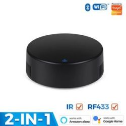
    Black circular electronic device with Bluetooth, WiFi, and Tuya labels, featuring IR and RF433 functions.
    I confirm that it use CBU/BK7231N and SH4/CMTOV30
    I have draw a mini diagram
    
      ┌─────────────────────────────────────────────────────────────────────┐
      │                                                                     │
      │                      CBU                                            │                  SH4
      │         ┌──────────────────────────┐                                │           ┌──────────────┐
      │         │                          │                                │           │              │
      └───────► │ P14                 P15  │                                │           │ NC       ANT │
                │                          │                                │           │              │
      ┌───────► │ P16                 P17  │                                │           │ GPIO3     NC │
      │         │                          │                                │           │              │
      │ ┌─────► │ P20                  P9  │ LED                            │           │ GND      GND │
      │ │       │                          │                                │           │              │
      │ │   ┌─► │ P22                 CEN  │                                └────────── │ SCLK      NC │
      │ │   │   │                          │                                            │              │
      │ │   │   │ ADC                 P28  │                                      ┌──── │ SDIO      NC │
      │ │   │   │                          │                                      │     │              │
      │ │   │   │ RX2                 RX1  │                                  ┌───┼──── │ CSB    GPIO1 │ ────────────────┐
      │ │   │   │            P P G 3       │                                  │   │     │              │                 │
      │ │   │   │ TX2  P P P 2 2 N V  TX1  │                              ┌───┼───┼──── │ FCSB   GPIO2 │ ─────────────┐  │
      │ │   │   │      8 7 6 6 4 D 3       │                              │   │   │     │              │              │  │
      │ │   │   │                          │                              │   │   │     │ VCC      GND │              │  │
      │ │   │   └──────────────────────────┘                              │   │   │     │              │              │  │
      │ │   │          I I ▲ ▲                                            │   │   │     └──────────────┘              │  │
      │ │   │          R R │ └────────────────────────────────────────────┘   │   │                                   │  │
      │ │   │              │                                                  │   │                                   │  │
      │ │   │          R T └──────────────────────────────────────────────────┘   │                                   │  │
      │ │   │          X X                                                        │                                   │  │
      └─┼───┼─────────────────────────────────────────────────────────────────────┘                                   │  │
        │   │                                                                                                         │  │
        │   │                                                                                                         │  │
        │   │                                                                                                         │  │
        │   └─────────────────────────────────────────────────────────────────────────────────────────────────────────┘  │
        │                                                                                                                │
        └────────────────────────────────────────────────────────────────────────────────────────────────────────────────┘


    Also the CBU use the 3 wires SPI (SDIO) protocol to communicate with SH4.
    And in the log when we use the RF is mention "CMT2300A_IsExist" so it seems that we can use the CMT2300A as reference.

    On the product page of CMT2300A, there is two demo with some source code (where there is a function "CMT2300A_IsExist"):
    * CMT2300A_DemoEasy_v1.2
    * CMT2300A_Demo(STM32)V1.0.1

    I don't know if this can help you and if we can use it in OpenSource project, let me know.
  • #11 20809098
    p.kaczmarek2
    Moderator Smart Home
    Very nice find! It indeed seems like CMT2300A-EN-Rev0.7.pdf document contains all the information we need. I need to find time to check this out.
    Helpful post? Buy me a coffee.
  • ADVERTISEMENT
  • Helpful post
    #12 20809439
    DeDaMrAz
    Level 19  

    Just so we have some idea of what we are dealing with, attached here is a schematic of a version of this device that I have.

    We were planning on working on this device for the longest time but there is always something more important :)

    I think we will begin soon though.
  • #14 21094187
    merni99
    Level 4  

    I just bought the S11. Any progress on supporting/implementing S11 with SH4 RF module?
  • #15 21155943
    olivluca
    Level 6  
    I just got a moes UFO-R2-RF and it uses the same CBU/SH4 combo. I didn't check (yet) if the connections are the same. (edit: I checked now and they seem to match).
    Any progress on this module?
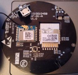
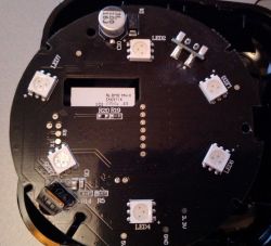
    Electronic board with CBU modules and antenna Image of a circular printed circuit board with various electronic components such as LEDs and capacitors.
  • #16 21156233
    p.kaczmarek2
    Moderator Smart Home
    We've started working on new IR library that can more or less capture data and send Flipper Zero IR format:
    https://www.elektroda.com/rtvforum/topic4062643.html#21137604
    https://www.elektroda.pl/rtvforum/topic4062643.html#21137604
    Helpful post? Buy me a coffee.
  • #17 21156286
    olivluca
    Level 6  
    And what about the RF part?

    Added after 5 [minutes]:

    thementor wrote:


    That link doesn't work, but there is this one

    https://github.com/tuya/tuya-bsp-gpl-public-c...main/driver_src_tuya/ty_driver/src/subg/radio

    And this one (I searched github for the RF_StartRx function)

    https://github.com/jabc1/CMT2300A_DemoEasy

    Added after 11 [hours] 17 [minutes]:

    Seaching "cmt2300a" on github gives some interesting results, e.g.:
    https://github.com/tbnobody/OpenDTU/tree/master/lib/CMT2300a
    (which is part of an esphome component)
    the parameters files are for a different frequency (860 or 900 MHz) but using the one from the tuya driver should use the correct frequency.
  • #18 21162440
    olivluca
    Level 6  
    I'm trying to get the RF part working using libretiny
    https://github.com/olivluca/TestTuya
    So far no success.
    The spi part seems to be working (I tried with a bogus pin for data and it couldn't initialize the radio, with the correct definition it initializes, I can put it in RX mode and see the state transitions), but I see no data (the fifo is always filled with 0).
  • #19 21164026
    olivluca
    Level 6  
    I fixed the gpio assignment in the code and I'm using the RF parameters (registers from 0x00 to 0x5f) in the csv of the first post.
    With that I had some limited success: I can see some data but it's not correct (i.e. I see the same bytes for more than one button of my remote) besides I see some stray codes (maybe there's another transmitter nearby).
    It turns out you can generate the parameters using the RFPK tool, available here https://www.hoperf.cn/ic/rf_receiver/CMT2219A.html, the register values can be exported to a text file then a simple python script will convert it to the cmt2300a_params.h
    The problem is I cannot find a way to do the reverse (i.e. from the registers derive the parameters) so I can tweak it to see if I can decode my remote. The datasheet doesn't document most of them, it just says to use the RFPK tool.
    @JustAnotherUser did you per chance capture the spi conversation while trying to learn some buttons?
    Maybe it uses different sets of parameters doing several attempts.


    Ç
  • #20 21181007
    olivluca
    Level 6  
    I bit the bullet, soldered some more cables and captured the spi communication of the original firmware.
    Now sending mostly works (sometimes I have to repeat the same button more than once before it is received), receiving is still not working.
    Oh, and the trick is to use direct mode, avoiding the decoding/encoding on the cmt2300a and its fifo.

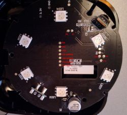
    Edit: I labeled the test points, P6 (CSB) and P16 (FCSB) are not available on this side of the pcb, you have to get them from the cpu on the other side.
    Circuit board with test point markings and LEDs
  • #22 21225830
    divadiow
    Level 34  
    DeDaMrAz wrote:
    We were planning on working on this device for the longest time but there is always something more important :)

    @DeDaMrAz @p.kaczmarek2 I'm going to pickup one of these IR devices with SH4 if that's any help with testing in the future...
  • #24 21538886
    alaei
    Level 1  
    @olivluca Thanks for the work.https://github.com/olivluca/tuya_rf works like a charm.
    It would be wonderful if we could extract formula RFPK tool is using and add support for other frequencies. One simple idea is to get multiple const configuration for example 315/433 and switch between those.
  • #25 21538942
    olivluca
    Level 6  
    @alaei as I said, I couldn't succeed in generating a working configuration using RFPK. You could try generating a random configuration for 433MHz, another for 315 and see what are the differences, then "plug" those differences in cmt2300a_params_captured.h.

Topic summary

The discussion revolves around the CBU/BK7231N and SH4/CMTOV30 Wi-Fi IR+RF Remote Control (S11). Participants explore the SPI communication protocol used by the RF module, referencing the CMT2300A datasheet for detailed protocol information. There are inquiries about obtaining original firmware dumps after flashing OpenBeken, with insights shared on the challenges of restoring stock firmware due to unique serial numbers and keys. Users share their experiences with firmware modifications, including attempts to capture SPI communication and develop an ESPHome component for RF functionality. The conversation also touches on the development of an IR library and the need for further testing and collaboration on the RF aspects of the device.
Summary generated by the language model.
ADVERTISEMENT