Purpose and principle of operation
There are libraries for Arduino used to control devices via IR. However, I decided to solve it in a different way - I wanted to create a learning system, i.e. remembering the codes from the original remote control. This allows you to control a whole range of devices such as air conditioners, light chains, disco balls, etc. The main task of the system was to work on the on/off basis, but of course you can record and play any sequence of pulses and thus simulate pressing any button on the remote control or pressing sequence. The system also has an additional functionality - signaling whether the device is switched on or not. Sometimes we are far from the controlled system and we want to be sure that, for example, the air conditioner has been turned off. On the occasion of developing software on Arduino, I decided to use GPT chat to create some code. Read on to see what came of it.
A bit of history, or why the system was created?
At home I have a fireplace and a DGP. I decided to earn extra DZP, i.e. Cold Air Distribution. For this purpose, I placed a monobloc room air conditioner in the attic, which I connected to a fireplace fan and an additional fan blowing air into the rooms. The system was controlled by a remote control, but I won't go to the attic every time I need to turn the air conditioner on or off. An extension cord had to be made. The first version was wired (TSOP receiver and 38 kHz generator. It worked well, but after changing the furniture, the cable connecting the receiver with the transmitter looked very ugly. The next solution was based on a ready-made 433 MHz radio extension cable (the one in the shape of a UFO). It did not work perfect - sometimes there were problems with turning off the air conditioner, but the biggest problem was the automatic switching on of the air conditioning (luckily in ventilation mode). system and replaced it with the presented solution - sending remote control commands via Wi-Fi, and in conjunction with the rest of the smart home infrastructure - the ability to control from any place with Internet access.
System construction
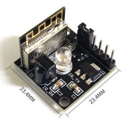
Since I do everything on ESP8266 and Arduino, the choice of platform was obvious. It remained to create such a circuit, and basically two circuits - one for teaching (reading) and the other for transmitting. I was thinking about building it myself, or about modifying SONOFF Basic. However, I found this module:

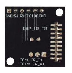
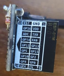
It has both a receiver and a transmitter in it, and it's connected to the ESP8266. The pins necessary for programming are easily accessible and well described:

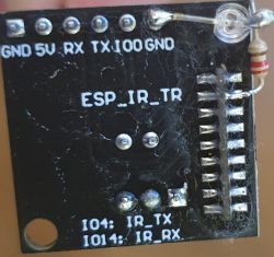
So I decided to buy such a module. I bought 3 pieces because I wanted to convert one chip into a reader and the other into a transmitter (the third is a spare). Later, I changed the concept and each module can work in both receiver and transmitter mode. The system is not perfect - the diode operating in visible light is missing. Such a diode turns out to be very useful during testing - you can blink in self test and blink during transmission. You just know what's going on. It was very important for me, because after the first programming "with cables", I immediately switch to OTA and do not play with RX, TX, which is why my system was equipped with such a diode:


I used a red "bright" 3mm LED in a clear case connected by a 220R resistor to the ESP. I recommend such diodes - they shine brightly at a current of 1-2 mA, and the colorless casing leaves no doubt whether the diode is on or not at a given moment.
Reading keyfob keys
The sequences read from the buttons on the remote controls had to be stored somewhere. I decided that the "database" will be a single json file, in which individual remotes will be saved, and in each remote - buttons. It looks something like this (number sequences have been shortened for presentation):
Code: JSON
Each remote (identified by name) has two global parameters: frequency (in Hz) and duty cycle (in %), and of course a list of buttons with times. The unit of time is 10 µs, so the number 290 corresponds to 2.9 ms. Numbers cannot be larger than 16 unsigned bits, i.e. approx. 655 ms. The first number is the signal time, the second number is the pause time, and so on. The last number is always the signal time. The sequence of numbers itself (as 16-bit binary data) is provided by ESP. There was a problem how to add it to the "base". For this purpose, auxiliary software was created in the form of a website and a PHP script:
File "button.htm":
Code: HTML, XML
button.php:
Code: PHP
The script works as a demo remote. We can send any button code to any ESP. The send() function shows how to send the code. One of the parameters is nrir – this is the name of the specific system and the code compiled for it. In the example shown, it is "IRX1" (with APname).
If we have several chips, then we have to compile the code many times, changing the APname to IRX2, IRX3, etc. each time. For me, each chip asks for an OTA update at startup, but this query also records the APname and IP on the server side. That's why I always know what IP a specific system is at a given moment:
Code: PHP
All this can be changed - just give the systems a specific fixed IP.
Remote control commands can also be sent using GET, e.g.:
http://192.168.1.20/IR.php?action=IRget&nrir=IRX1&remote=TV-SONY&button=Power
Summary
The proposed solution is very universal. Allows multiple devices to be controlled by multiple IR transmitters. Codes can be uploaded to the database also after starting the whole thing. Each of the transmitters can send any sequence and does not require reprogramming for this purpose. Unfortunately, such versatility complicated the solution in terms of presentation on the electrode. Finally, a few remarks on the presented transmitter/receiver system. Well, even before the purchase, I noticed that the IR diode is controlled by a transistor without any current-limiting resistor. It is interesting because the whole is powered by a stabilizer that can give up to 1 A, which is far too much for an IR diode. However, the system works, and the diode did not burn out. Probably the current limiter is a transistor whose beta decreases strongly with the current, which is apparently enough with a 1 kΩ resistor on the base. The system has one more disadvantage - the placement of the IR diode. It is practically impossible to build it (the diode is lower than the ESP plate). Therefore, it should be solved in a different way - either the diode should be soldered to the other side, or led out on a cable. In any case, its original location is unfortunate.
Cool? Ranking DIY


