 .
.
Here I will describe the implementation process of sending an IR signal based on a PWM and a timer. The signal sent like this from the microcontroller will be able to control the air conditioning. In addition, the signal format used will be compatible with what Flipper Zero captures, allowing the signals captured in this way to be used to send them from my platform. I will implement the topic based on the MCU on which I am doing my project, but I think the steps shown here will be analogous on other platforms as well.
Plan of action .
In the previous topic we looked at the IR signal captured by Flipper Zero:
Building an IR signal, captured in Flipper Zero, written in raw format .
So we already know that you will need:
- PWM, in this case 38kHz with adjustable fill
- some form of timer to be able to wait a given time to switch the PWM on/off
As a reminder, this is the format we want to send:
name: Power
type: raw
frequency: 38000
duty_cycle: 0.330000
data: 2204 708 834 1342 882 1344 837 632 836 1392 836 615 723 738 836 633 861 684 835 658 838 710 835 657 838 656 837 641 723 762 838 1397 727 101537 2257 704 761 1417 884 1342 762 737 731 1467 836 612 828 634 760 707 787 760 835 658 761 786 835 658 761 733 836 637 827 660 763 1473 726
This means that we need to turn on the 38kHz PWM with a fill of 33%, leave it on for 2204 us, then turn it off and wait 708 us, then turn it on again, and so on.
So we need to have some kind of table into which we write these timing values and operate according to them.
It is necessary to wait for these times somehow. I see two options here:
- set the timer anew with each time to a given value, after which the interrupt will occur
- rigidly choose some unit of timer precision
For simplicity, I have chosen the second way. With a sufficiently small interrupt period, errors will be negligible. Looking at these timer values, I decided to call the timer every 50 us.
Starting the timer .
So we start the timer. This looks different depending on the platform. I implemented this on a BK7231, so documentation was practically non-existent. I had to search through the Chinese SDK myself for what and how. Here is the timer launch:
Code: C / C++
In addition, in order to check if the timer works, I decided to "wave" some GPIO. Setting the pin to output mode:
Code: C / C++
Well, and our ISR - Interrupt Service Routine - handling the interrupt from the timer:
Code: C / C++
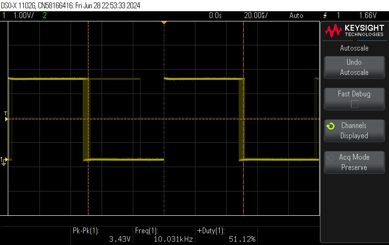
Uploading, testing:
 .
.
Indeed, it all comes together. The whole thing could still be significantly optimised by replacing the pin handling by a function with direct register operations, but for now we're just running the timer, so I'll skip that.
Run the PWM .
Similarly, we now need to run PWM. All for now as a separate example. On my BK7231 it looks like this:
Code: C / C++
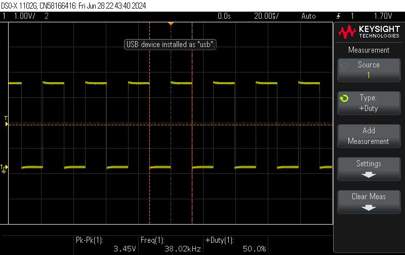
26000000 is the MCU clock frequency, which is 26MHz. We divide it by 38kHz to get the PWM period value. Then we set the fill to half the period - 50%. It works:
 .
.
Starting the time queue
Now we need to consider how we will represent the raw data in memory.
Let's make it as simple as possible - the circular buffer can be introduced later. Let's create an array of fixed size:
Code: C / C++
Now you need to remember what is next in the queue to be sent - let's say it will be a pointer to a given element in the array. When it is zero, it means we have sent everything.
Code: C / C++
You also need to know where to stop - let's just enter a stop indicator.
Code: C / C++
Now let's still set the timer period and the variable counting the elapsed time. By the way, we need to remember the state (we are sending PWM or not) so that we can convert it to the opposite when the timer expires:
Code: C / C++
And now our ISR, however, without PWM to start with - just waving a pin:
Code: C / C++
The above code counts how much time has elapsed, compares the elapsed time with the next threshold and if the threshold has been passed, the code 'jumps' it and subtracts its value from the current time (so as not to accumulate an error).
I also added command parsing to this in the format:
Send 100,500,300,500,100
This topic is not about parsing ASCII text into a buffer, but I'll mention that I used strtok anyway - code for reference:
Code: C / C++
The only important thing here is to remember not to start sending data prematurely, during parsing. This is why I set the "cur" pointer to the first element of the array at the end, already after parsing.
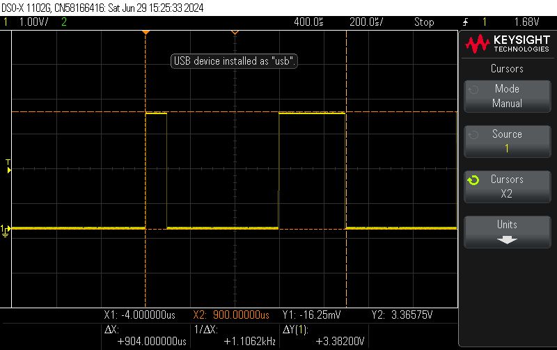
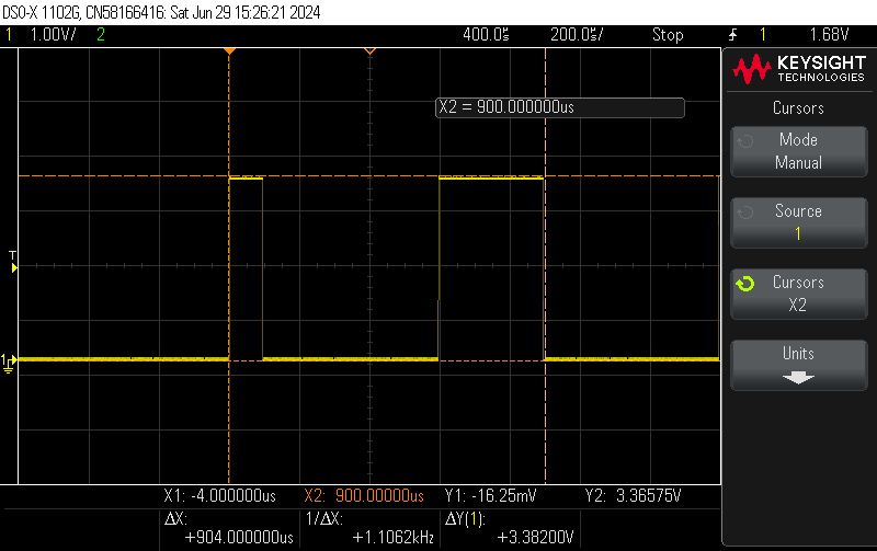
We test - we send the "data":
 .
.
 .
.
It all adds up. The high state is about 100us, then a low of 500us and again a high of 300us. This is what I have specified in the file.
PWM comes into action .
Since swiping the pin according to the times already works, PWM can be plugged in. Basically we just change a few lines. Depending on the state (sending or not), we set the appropriate fill (although you could just as well turn off the whole PWM...):
Code: C / C++
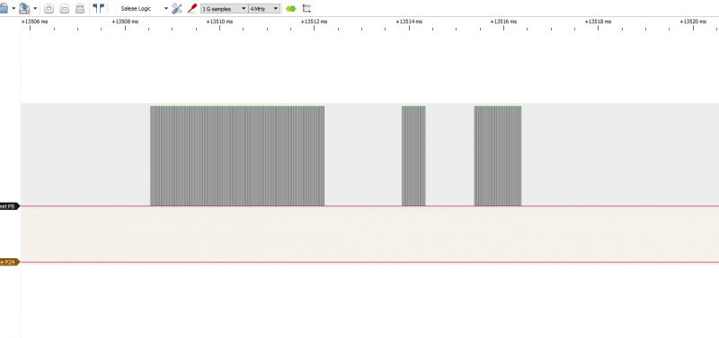
Time to test this. In my environment, everything is wrapped in text commands that look roughly like this:
// start the driver
startDriver IR2
// start timer 50us
// arguments: duty_on_fraction, duty_off_fraction
StartTimer 50 0.5 0
// send data
Send 3500, 1500, 500, 1000, 1000, 500,
Example result (screenshot from Sigrok):
 .
.
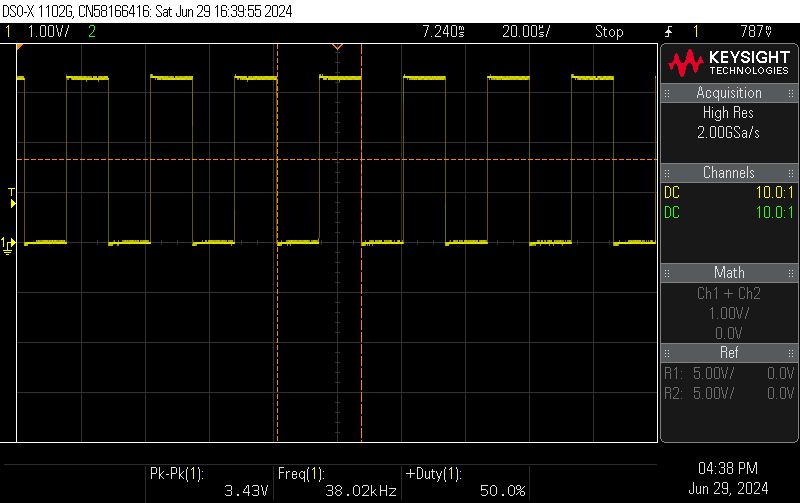
When zoomed in you can see the PWM (here from the oscilloscope):
 .
.
Another example:
// start the driver
startDriver IR2
// start timer 50us
// arguments: duty_on_fraction, duty_off_fraction, pin for sending (optional)
StartTimer 50 0.5 0
// send data
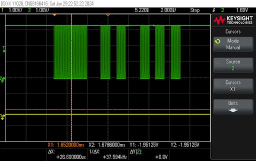
Send 3200,1300,950,500,900,1300,900,550,900,650,900
The result - looks good.
 .
.
One could already test with air-conditioning, but there is still a moment....
Minor optimisations
One could end here - but are we sure?
Remember that time and precision are of the essence here, and library functions are not always optimal.
Let's consider how we update the PWM:
Code: C / C++
Does it look innocent? But what's hiding under the hood?
Code: C / C++
This just brings up another function... what is sddev_control?
Code: C / C++
Well, it doesn't look very efficient.
First of all, here is an iteration and comparison of .... character strings? What is PWM_DEV_NAME?
Code: C / C++
Yes, these are the subtitles.
And what does the array they iterate look like?
Code: C / C++
That's pretty long. And without a hash table? No no, it can't be like that, it needs to be optimised.
Let's see where the call finally goes.
Where is CMD_PWM_SINGLE_UPDATA_PARAM used?
Only in PWM is there a big switch with multiple cases:
Code: C / C++
And this ultimately calls:
Code: C / C++
In summary, I see a few things to improve here:
- firstly, you can write directly in the IR driver after registers instead of calling these many functions as in the SDK
- secondly, these variables can be fetched once and kept in memory afterwards:
Code: C / C++
- thirdly, as I only change the first duty_cycle, the other REG_WRITEs can be omitted:
Code: C / C++
- fourthly, as we know that group will be constant, what does REG_GROUP_PWM0_T1_ADDR do? It's a macro;
Code: C / C++
This final address value can also be counted once and then held in memory....
I've done most of these optimisations, I'll be adding the rest. Whoever wants can find the code on my repository: https://github.com/openshwprojects/OpenBK7231T_App
Final test .
For our final test, we used the Galanz AUS-12HR53FA2/AS-12HR53F2F air conditioner:
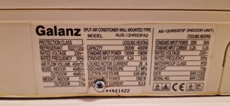 .
.
This air-conditioning does not have WiFi, but has a remote control with enough functions for comfortable use:
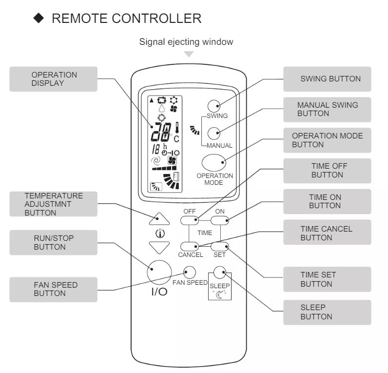 .
.
We captured the Flipper Zero command ON:
Filetype: IR signals file
Version: 1
#
name: Galanz_on
type: raw
frequency: 38000
duty_cycle: 0.330000
data: 3665 1547 605 1078 527 1151 507 498 605 415 584 415 584 1098 585 415 507 501 522 1152 507 1175 585 417 528 1154 506 497 502 523 579 1081 524 1160 550 493 584 1080 603 1077 503 502 600 416 583 1105 578 417 582 419 504 1178 582 445 477 503 599 416 583 416 506 500 524 499 579 417 506 492 507 523 579 417 582 415 508 496 553 451 601 416 583 421 501 500 549 468 584 1104 579 418 581 417 506 1176 583 416 507 503 546 1129 528 1156 504 499 550 450 601 417 583 418 505 523 526 469 583 416 507 1176 583 1101 582 417 582 418 505 500 601 417 582 419 504 1176 583 418 506 1179 580 1102 581 416 586 419 502 523 578 418 581 418 505 500 525 494 582 417 506 495 505 502 547 468 582 422 502 499 524 500 526 469 581 420 504 501 549 467 582 418 506 501 575 468 582 418 506 498 502 502 548 468 582 420 504 500 550 467 532 467 507 496 528 494 532 465 534 468 506 500 550 468 531 470 531 1177 531 1155 528 1133 550 1132 524 501 526 469 530 1152 531 467 534
We converted the command to the format for my firmware (times separated by commas) and.... the air conditioning started! .
[i]For the upload we used an 'IR blaster' from Tuya with OpenBeken uploaded.
Summary .
It looks like my IR upload is working. I'll still probably add 1:1 support for the same files that Flipper Zero creates, but that's already a matter of parsing the data, so it's not as interesting or important as the upload itself. Additionally, I think you could try setting the timer to pulse time instead of checking every 50μs, but I'll try to implement that later. At the moment I have met all the assumptions set for myself, so I am satisfied.
Has anyone reading implemented IR sending themselves, or does everyone use a ready-made solution - and if so, which one? A little art for art's sake for educational and hobby purposes is unlikely to hurt anyone.
Cool? Ranking DIY Helpful post? Buy me a coffee.


