Today we are looking inside a simple "smart" lighting sensor, which surprisingly was implemented by the manufacturer based on TuyaMCU, i.e. based on an additional microcontroller communicating with the WiFi module via UART. Here we will analyze their communication protocol and try to free this sensor from the cloud, although at the moment we will do it by replacing the WiFi module. Finally, we will provide a ready OpenBeken configuration for this sensor and check its operation with Home Assistant.
The topic was created in cooperation with @DeDaMrAz, I did not physically have this device at home, I only directed my friend's actions. All photos are also from a friend.
Sensor purchase
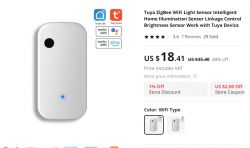
The sensor can be found under entries like "Tuya WiFi Light sensor illumination brightness sensor" and so on, you have to be careful whether you choose the Zigbee or WiF version:
The sensor is powered from USB, the cable is included:
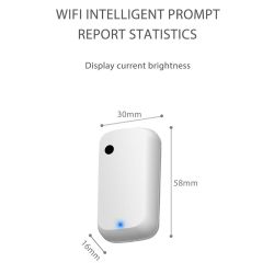
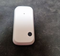
The sensor is quite small:
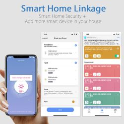
This is what it looks like in the Tuya app:
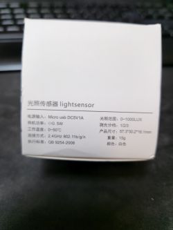
Original packaging:
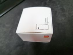
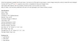
Lightsensor, GB 9254-2008, few details
Interior and communication protocol
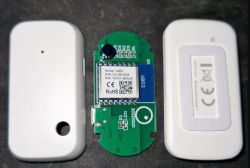
We look inside, pry the plastic cover:
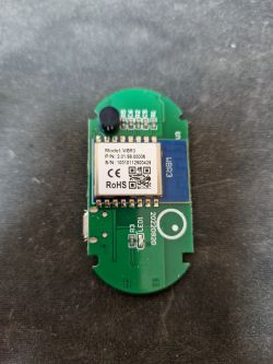
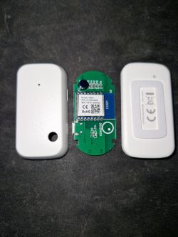
We have WBR3 here... I'm working on it, but it's not Beken. Date 2022-09-20.
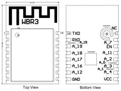 But what is on the other side of the PCB?
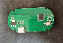
There is of course the AMS1117-3.3V LDO regulator to get 3.3V from 5V from USB, but we also see an additional microcontroller here.
It looks like this device is using TuyaMCU:
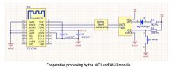
The TuyaMCU protocol was featured here:
https://www.elektroda.pl/rtvforum/topic3880546.html
We also have our own analyzer for this:
https://www.elektroda.com/rtvforum/topic3970199.html#20528459
Therefore, we launched the analyzer, sequentially collecting data on the RX and TX of the WiFi module. Bingo!
The most important interception of packets was made on the RX of the WiFi module. We look at what the MCU sends to us:
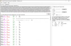
At first, apart from checking in, the MCU gave no measurements. This was due to the fact that it had to be paired.
Since then, the variables have appeared:
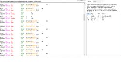
There is a "FindMe" option in the Tuya app that makes the LED blink. We also managed to overhear the change of its state, it is a boolean variable with dpID 101. The eavesdropping was made on the TX of the WiFi module (it is the WiFi module that sends its change to the MCU):
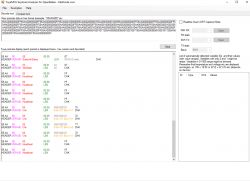
After the analysis, we assessed:
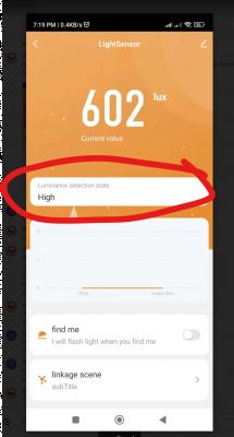
- dpID 6 is enumeration, lighting level, 0, 1 or 2
- dpID 7 is the illumination level in lux
- dpID 101 is "find me" option from Tuya application
The dpID6 in the app looks like this:
Firmware change?
Work on WBR3 is in progress, but a friend had a free CB3S module, so we soldered it in its place to test the TuyaMCU support code from OpenBeken:
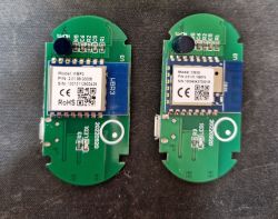
Then we prepared the autoexec.bat OpenBeken:
startDriver TuyaMCU

// always report paired
tuyaMcu_defWiFiState 4

setChannelType 1 Illuminance
setChannelLabel 1 Lux
linkTuyaMCUOutputToChannel 7 val 1

setChannelType 2 Toggle
setChannelLabel 2 FindMe
linkTuyaMCUOutputToChannel 101 bool 2

setChannelType 3 ReadOnly
setChannelLabel 3 LightLevel
linkTuyaMCUOutputToChannel 6 enum 3
The above code maps variables from TuyaMCU to OpenBeken channels. Sets them labels to display and channel types. Channel types then also determine how Home Assistant displays them.
Initially, we tried without "default wifi state 4", but without it, in the absence of MQTT, we would not get measurements. The MCU must "think" that it is paired with the cloud to give measurements.
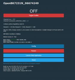
Success! We have measurements on the OBK panel. Now it's still worth doing Home Assistant Discovery, which is already automatic with us. Below are screenshots before the introduction of the Illuminance channel type:
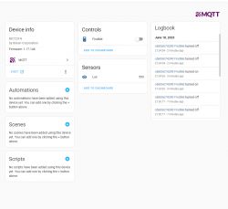
Even after adding this lighting level enumeration:
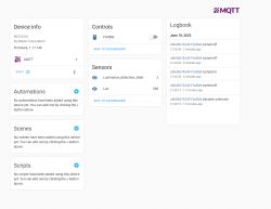
Everything works, although ultimately this lighting level (enumeration) will get its channel type so that it is displayed in text on the HA panel. And if necessary, you can always add it yourself via configuration.yaml.
Pairing button on TuyaMCU
It is also worth paying attention to what TuyaMCU sends when we press the pairing button. This button is connected to the microcontroller, not to the WiFi module:

Packet 55AA0002000001 is sent, which is packet type 02 with 00 00 bytes of data (that is, no data, the last byte, 01 here, is the checksum).
Summary
It was very simple, and after the OBK port to WBR3, you won't even need to solder the module. The TuyaMCU support code worked well in the new environment and did not require any changes. Everything works.
The only thing that puzzles me is why this sensor was implemented on TuyaMCU at all, i.e. why is there an additional microcontroller to perform lighting measurements?
Thank you again @DeDaMrAz for your cooperation, it went very quickly and smoothly, and we on the forum have not yet had an analysis of the inside of the USB lighting sensor, so it's also always something new for our department. Thank youyou!
Cool? Ranking DIY Helpful post? Buy me a coffee.


