logo elektroda
logo elektroda
X
logo elektroda

[BK7231N / CB3S] Generic Tuya Water Pump flashing and setup OpenBK7231N_QIO_1.17.240.bin

SoundreameR 2439 2
ADVERTISEMENT

  • Hello again! It's been a while since I last posted. Found this ultra-cheap house plant water pump from China and I was pretty determined to make it work with open source firmware, whatever is inside. [BK7231N / CB3S] Generic Tuya Water Pump flashing and setup OpenBK7231N_QIO_1.17.240.bin

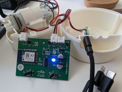
    Turns out there's a CB3S inside along with some unlabeled custom MCU in a SOP16 package. Probably designed that way to facilitate battery powered mode, which the PCB does seem to be fully capable of doing but the pump plastic housing was refactored and modified for USB powering instead. The two buttons on the front panel are wired through the custom MCU which is connected only via P14 to the CB3S. Luckily the CB3S directly controls the two LEDs and the pump motor through P7 and P8.

    Using hid_download_py I managed to upload OpenBeken to the module from the third attempt using the power-cycling method because of lack of hands to ground the reset pin.
    sudo ./uartprogram /home/ivan/Downloads/OpenBK7231N_QIO_1.17.240.bin -d /dev/ttyUSB0 -w -s 0x0 -u
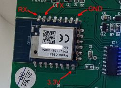

    Close-up of a circuit board featuring a CB3S module with labeled RX, TX, GND, and 3.3V pins along with other components.

    It took me some trial and error but eventually I figured out the two buttons could be utilized by listening for short click and long hold on the same input as it seems the custom MCU is simulating a single button on that input pin. Tapping the wifi button generates a long press event and tapping the pump power button generates a short click event. Pressing the buttons any other way doesn't produce any different events. That's just how the custom MCU behaves.

    Adding
    backlog AddEventHandler OnClick 14 ToggleChannel 1; AddEventHandler OnHoldStart 14 backlog OpenAP
    to the startup gives the two buttons somewhat useful functions of toggling the pump on and off and setting the board into AP mode respectively.

    Adding template as response to this post after I get a thread ID.
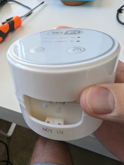
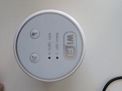
    The image shows a hand holding a small white water pump with two buttons and Wi-Fi symbols on its front panel. Top view of a water pump with WiFi and power buttons. Water pump control module with exposed PCB and wires.

    Added after 1 [minutes]:

    Here's the template I am using:

    {
      "vendor": "Tuya",
      "bDetailed": "0",
      "name": "Tuya Generic Water Pump",
      "model": "WIFI-V1.11",
      "chip": "BK7231N",
      "board": "WIFI-V1.11",
      "flags": "1024",
      "keywords": [
        "CB3S",
        "BK7231N",
        "water",
        "pump"
      ],
      "pins": {
        "7": "Rel;1",
        "8": "WifiLED_n;0",
        "14": "Btn;2"
      },
      "command": "backlog AddEventHandler OnClick 14 ToggleChannel 1; AddEventHandler OnHoldStart 14 backlog OpenAP",
      "image": "https://obrazki.elektroda.pl/2842963700_1694381412_thumb.jpg",
      "wiki": "https://www.elektroda.com/rtvforum/viewtopic.php?p=20728797#20728797"
    }


    Cool? Ranking DIY
    About Author
    SoundreameR
    Level 3  
    Offline 
    SoundreameR wrote 5 posts with rating 1. Live in city Calgary. Been with us since 2023 year.
  • ADVERTISEMENT
  • #2 20728909
    p.kaczmarek2
    Moderator Smart Home
    Very good and comprehensive review. Futhermore, it's a new device to me. I haven't seen that one yet. Well done!

    So it's an USB-powered one? What kind of USB adapter is recommended, will 500mA be enough? Have you tried to measure the current consumption when motor is running?
    Helpful post? Buy me a coffee.
  • #3 20729728
    SoundreameR
    Level 3  
    Thanks! Good questions, but unfortunately I don't have a ready answer.

    The device is USB powered. The PCB is equipped for battery mode, all the necessary circuitry is there.
    The plastic housing even has a battery compartment for 4xAA, but the wiring is missing and there's a sticker explaining that for better performance stability you should use USB power instead.
    It has a micro USB and I don't remember seeing any power ratings anywhere, not on the device itself, nor in the store ad or the user manual that came with it.
    I've tested it through my laptop's USB and it's running fine, but perhaps a 1A adapter would be a reasonable choice.
    There are 2 beefy capacitors on the PCB so it should be fine.
    I haven't measured the actual current draw because I don't have the appropriate tools to do so. I've recently moved and all I have in terms of tools sums up to a questionable multimeter and a CP2102 USB to UART stick.


    Added after 8 [hours] 31 [minutes]:

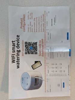
    Ok I checked the box again and found this pamphlet which suggests 600 mAh. So yeah, 1A should be more than enough.
    Promotional flyer showing a Wi-Fi controlled smart watering device.
ADVERTISEMENT