logo elektroda
logo elektroda
X
logo elektroda

Flashing OpenBK Firmware on CBU-IBEX with BK7231N MCU for WiFi Switch

keCho6oo 1986 6
ADVERTISEMENT
  • #1 20854078
    keCho6oo
    Level 2  
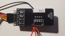
    I have this PC remote WiFi switch that i want to get working with this openbk firmware. I bought it from aliexpress and it has an CBU-IBEX module with a BK7231N MCU. I flashed the openbk firmware successfully after soldering wires to the corresponding pins. I extracted the json with the bk7231flasher tool (see below). The BK chip communicates with an STC 8P1K17S2 Microcontroller via serial 9600 baud protocol.
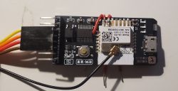
    Close-up of a WiFi remote switch module with visible wires and connectors. Electronic module with soldered wires on a white background.
    {
    	"baud":"9600}e",
    	"ap_passwd":"null",
    	"country_code":"null",
    	"bt_mac":"null",
    	"bt_hid":"null",
    	"prod_test":"false",
    	"fac_pin":"rtbhfbuii82scjrp0UAtls_ca_cnt00hf8Agw_di)JBgw_wsm{abi",
    	"id":"null",
    	"swv":"2.0.2",
    	"bv":"40.00",
    	"pv":"2.2",
    	"lpv":"3.3",
    	"pk":"na90jncjlvw5t0ba",
    	"firmk":"key83r5jq9qqeaxt",
    	"cadv":"1.0.3",
    	"cdv":"1.0.0",
    	"dev_swv":"1.0.0",
    	"s_id":"null",
    	"dtp":"9",
    	"sync":"0",
    	"attr_num":"0",
    	"mst_tp_0":"0",
    	"mst_ver_0":"null",
    	"mst_tp_1":"0",
    	"mst_ver_1":"null",
    	"mst_tp_2":"0",
    	"mst_ver_2":"null",
    	"mst_tp_3":"0",
    	"mst_ver_3":"null }W",
    	"auth_key":"dxh9Hm04AlCjK6VNTVIAx84JKVFDGqWP",
    	"md":"0",
    	"random":"0",
    	"wfb64":"1",
    	"stat":"0",
    	"token":"null",
    	"region":"null",
    	"reg_key":"null",
    	"dns_prio":"00{abi",
    	"mst_v{uuid":"ea3dacdd50560de1",
    	"psk_key":"T8Co7KlU9dp3tUa0QpAZpRfkcPtGvJKRAQmlW",
    	"ap_ssid":"SmartLife",
    	"lckey":"null",
    	"h_url":"null",
    	"h_ip":"null",
    	"hs_url":"null",
    	"hs_ip":"null",
    	"hs_psk":"null",
    	"hs_psk_ip":"null",
    	"mqs_url":"null",
    	"mqs_ip":"null",
    	"mq_url":"null",
    	"mq_ip":"null",
    	"ai_sp":"null",
    	"ai_sp_ip":"null",
    	"mq_psk":"null",
    	"mq_psk_ip":"null",
    	"time_z":"null",
    	"s_time_z":"null",
    	"wx_app_id":"null",
    	"wx_uuid":"null",
    	"dy_tls_m":"0",
    	"cloud_cap":"0",
    	"psk21_key":"null }{nc_tp",
    	"ssid":"null",
    	"passwd":"null",
    	"mode":"rw",
    	"property":"{type",
    	"{type":"obj",
    	"type":"enum}",
    	"cnt":"0}3Awf_start_md35RBem_sys_envbk7231n{key"
    }
    
  • ADVERTISEMENT
  • #2 20854333
    p.kaczmarek2
    Moderator Smart Home
    This looks like a TuyaMCU device. Do you have a 2MB flash backup? Have you tried running TuyaMCU driver and requesting dpIDs from device? Have you checked our docs, for TuyaMCU sample configs:
    https://github.com/openshwprojects/OpenBK7231T_App/blob/main/docs/autoexecExamples.md

    You could have also waited with flashing and done TuyaMCU packets capture first, they are sent on UART 1 port, both TX and RX is used, communication is bidirectional. You can analyze them with our tool: https://github.com/openshwprojects/TuyaMCUAnalyzer
    Helpful post? Buy me a coffee.
  • ADVERTISEMENT
  • #3 20854340
    keCho6oo
    Level 2  

    Yes, I have a backup. Can I write it back and then use the TuyaMCU Analyzer?
  • ADVERTISEMENT
  • #4 20854346
    p.kaczmarek2
    Moderator Smart Home
    Yes, it should be possible to do it, just enable backup restore in advanced options of flasher.

    Just to be sure - the WiFi module is connected to the MCU via RX1 and TX1?
    Helpful post? Buy me a coffee.
  • #5 20858732
    keCho6oo
    Level 2  

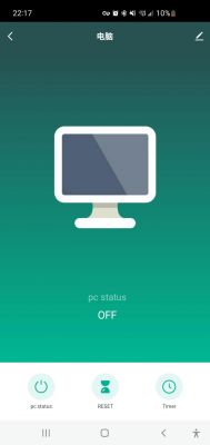
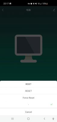
    So I flashed back the original Tuya Firmware. Seems to work (Shows up in Smart Life app and blinks). The CBU-IPEX module has second RX2 TX2 pins but these seem to be not used. I only can see traces from RX1 TX1 (16,15) Pins that go to the ST MCU.
    Using the TuyaMCUexplorer I was able to decode the messages


    This is for pressing the on button in the Smart Life app.
    Received by WiFi module:
    55 AA	00	06		00 05	0101000101	0E	
    HEADER	VER=00	SetDP		LEN	dpId=1 Bool V=1		CHK	
    Reset shows up in app(?)
     [url=https://obrazki.elektroda.pl/8085786800_1702416111.jpg][img]https://obrazki.elektroda.pl/8085786800_1702416111_thumb.jpg[/img][/url] 
    Received by WiFi module:
    55 AA	00	00		00 00		FF	
    HEADER	VER=00	Heartbeat		LEN		CHK	
    Received by WiFi module:
    55 AA	00	06		00 05	0101000101	0E	
    HEADER	VER=00	SetDP		LEN	dpId=1 Bool V=1		CHK	
    Received by WiFi module:
    55 AA	00	06		00 05	6504000100	74	
    HEADER	VER=00	SetDP		LEN	dpId=101 Enum V=0		CHK	
    Force reset
    Received by WiFi module:
    55 AA	00	06		00 05	6504000101	75	
    HEADER	VER=00	SetDP		LEN	dpId=101 Enum V=1		CHK	
    Received by WiFi module:
    55 AA	00	00		00 00		FF	
    HEADER	VER=00	Heartbeat		LEN		CHK	
    Received by WiFi module:
    55 AA	03	07		00 05	01 01 00 01 00 		11	
    HEADER	VER=03	State		LEN	dpId=1 Bool V=0	CHK	
    Received by WiFi module:
    55 AA	03	00		00 01	01	04	
    HEADER	VER=03	Heartbeat		LEN	01	CHK	
    Received by WiFi module:
    55 AA	03	01		00 2A	7B2270223A226E6139306A6E636A6C76773574306261222C2276223A22312E302E30222C226D223A307D	C1	
    HEADER	VER=03	Product		LEN	{"p":"na90jncjlvw5t0ba","v":"1.0.0","m":0}	CHK	
    Received by WiFi module:
    55 AA	03	02		00 00		04	
    HEADER	VER=03	McuConf		LEN		CHK	
    Received by WiFi module:
    55 AA	03	03		00 00		05	
    HEADER	VER=03	WifiState		LEN		CHK	
    Received by WiFi module:
    55 AA	03	00		00 01	01	04	
    HEADER	VER=03	Heartbeat		LEN	01	CHK	
    Received by WiFi module:
    55 AA	03	03		00 00		05	
    HEADER	VER=03	WifiState		LEN		CHK	
    Received by WiFi module:
    55 AA	03	03		00 00		05	
    HEADER	VER=03	WifiState		LEN		CHK	
    Received by WiFi module:
    55 AA	03	07		00 05	01 01 00 01 00 		11	
    HEADER	VER=03	State		LEN	dpId=1 Bool V=0	CHK	
    Received by WiFi module:
    55 AA	03	07		00 05	08 01 00 01 01 		19	
    HEADER	VER=03	State		LEN	dpId=8 Bool V=1	CHK	
    Received by WiFi module:
    55 AA	03	07		00 05	28 01 00 01 00 		38	
    HEADER	VER=03	State		LEN	dpId=40 Bool V=0	CHK	
    Received by WiFi module:
    55 AA	03	07		00 05	26 04 00 01 00 		39	
    HEADER	VER=03	State		LEN	dpId=38 Enum V=0	CHK	
    Received by WiFi module:
    55 AA	03	07		00 05	65 04 00 01 02 		7A	
    HEADER	VER=03	State		LEN	dpId=101 Enum V=2	CHK	
    

    Smart Life app interface showing computer status as off.
    Smart Life app interface with computer icon and reset options.
  • #6 20858746
    p.kaczmarek2
    Moderator Smart Home
    There are few dpIDs. Have you tried to narrow down which dpID is what? It would be very useful for us to know what's the meaning of each of them.

    For example, try toggling something in Tuya app (like first relay) and observe which dpId changes?

    For example, which dpId is responsible for timer variable?

    Can you also post some photos of your device? I haven't seen that one yet
    Helpful post? Buy me a coffee.
  • ADVERTISEMENT
  • #7 20858792
    keCho6oo
    Level 2  

    Photos are in the first comment. I described before every dump what the cause was. I wasn't able to test the inputs. There is an optocoupler to detect whether the power LED of a PC is on. You plug this thing into a PC motherboard (which I have not done yet) and connect it via USB to power it when the PC is off.

Topic summary

The discussion revolves around flashing OpenBK firmware on a CBU-IBEX WiFi switch equipped with a BK7231N MCU. The user successfully flashed the firmware after soldering connections and extracted JSON data using the bk7231flasher tool. The device communicates with an STC 8P1K17S2 microcontroller via a 9600 baud serial protocol. Responses suggest using the TuyaMCU driver to request dpIDs and analyze communication packets. The user confirmed the restoration of the original Tuya firmware, which allowed the device to function with the Smart Life app. They decoded messages related to device control and were advised to identify dpIDs for further functionality testing.
Summary generated by the language model.
ADVERTISEMENT