logo elektroda
logo elektroda
X
logo elektroda

[BK7231N - CBU] WD-01ADE Tuya water pump with WiFi - Unable to flash

drkbg 2577 15
ADVERTISEMENT
  • #1 20751807
    drkbg
    Level 4  

    1. So I am using CH340, connected RX, TX, 3v3, and GND.
    2. That blue diode stays solid for a second then goes blinking.
    3. I start the BK7231 GUI Simple Flasher.
    4. Choose the correct COM port, click on the flash firmware.
    5. I am asked to shorten GND and CEN.
    6. I shorten GND and CEN, and the blue diode goes off, goes solid on for a second, and then starts flashing again.
    7. The flasher still continues with prompting me to shorten CEN and GND.

    What am I doing wrong?
    I guess what happens with the diode means that I am succeeding in reboot?
    I also tried reversing TX and RX but no luck.

    Should I have the 3.3 external power supply also connected?
  • ADVERTISEMENT
  • #2 20751942
    p.kaczmarek2
    Moderator Smart Home
    Can you post a photo of the setup?
    drkbg wrote:

    5.I am asked to shorten GND and CEN

    It is better to do a power cycle then, disconnect and reconnect power ( reliable 3.3V), I do not even solder CEN
    Helpful post? Buy me a coffee.
  • #3 20752106
    drkbg
    Level 4  

    p.kaczmarek2 wrote:
    Can you post a photo of the setup?

    Will do later, as I already disconnected everything.

    p.kaczmarek2 wrote:

    It is better to do a power cycle then, disconnect and reconnect power (reliable 3.3V), I do not even solder CEN


    Does this mean that I should power the device via the power port to an external 3.3V additionally to 3.3V from the CH340?
  • #4 20752556
    p.kaczmarek2
    Moderator Smart Home
    I never power device directly from 3.3V of CH340. My CH340 dongle cannot provide enough current for programming to success. I always use external LDO, like AMS1117-3.3V.

    However, some people may have other USB to UART converters with better current capabilities.

    Have you seen our videos?
    https://www.youtube.com/@elektrodacom
    Helpful post? Buy me a coffee.
  • #5 20752597
    drkbg
    Level 4  

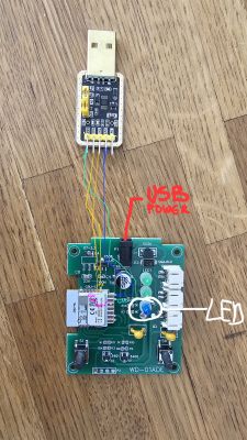
    The image shows a circuit board connected to a USB adapter using colored wires.

    My setup looks like this.

    So if I understand you correctly:
    1. I should not use the USB power connection during flashing.
    2. I should use something like AMS1117-3.3V to connect to the 3v3 and GND.

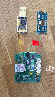
    At the end, it should look like this:

    Electronic connection setup using USB module, AMS1117, and PCB.
  • ADVERTISEMENT
  • Helpful post
    #6 20752646
    p.kaczmarek2
    Moderator Smart Home
    If this device has USB power, then the simplest way would be to:
    - connect GND, RX and TX from USB to UART converter
    - on USB to UART converter, connect VDD and 3.3V to select voltage levels 3.3V (at least on my USB to UART converter I need to do this, consult your own converter manual for more info)
    - connect power from USB as well
    - then, in flash tool, start flash, it will be doing "{getting bus" and waiting, while it waits, disconnect and connect power to the board, it should proceed with flashing

    The AMS1117-3.3V method is very universal, but if your board already has AMS1117-3.3V on board or any other 3.3V source, then you can just use that. Of course, it assumes that your board is not mains powered, because if it's mains powered and it has non-isolated power supply then you must never use this power supply while flashing, non-isolated power supplies ARE VERY DANGEROUS, you could fry your USB port
    Helpful post? Buy me a coffee.
  • ADVERTISEMENT
  • #7 20755310
    drkbg
    Level 4  

    Thanks a lot for the guidance. Indeed, the following worked for me:

    - Connect CH340G: GND to GND, TX to RX and RX to TX
    - Connect CH340G to USB
    - Connect power of device to USB
    - Start flasher, select firmware
    - Click on backup and flash
    - Shorten CEN & GND for less than a sec
    - Flashing starts

    I had a problem with connecting to WiFi but found that toggling power 5-6 times will result in safe mode with AP turned on again.

    I use the autoexec from this thread.
    setChannelType 1 toggle
    setChannelLabel 1 "Pump A"
    setChannelType 2 toggle
    setChannelLabel 2 "Pump B"
    setStartValue 1 0
    setStartValue 2 0
    setPinRole 16 Rel
    setPinChannel 16 1
    setPinRole 14 Rel
    setPinChannel 14 2
    setPinRole 8 Btn_n
    setPinChannel 8 1
    setPinRole 7 Btn_n
    setPinChannel 7 2
    setPinRole 20 WifiLED


    For some reason, in Home Assistant only Pump A is shown as an entity connected to the Pump, but both appear as switches.

    Thanks a lot!
  • #8 20755335
    p.kaczmarek2
    Moderator Smart Home
    Hey, can you also post YAML from Web App, so I can add this device to our teardowns list? Thanks!
    Helpful post? Buy me a coffee.
  • #9 20756133
    drkbg
    Level 4  

    Do you mean the template on the Config page of WebApp?
  • #10 20756421
    p.kaczmarek2
    Moderator Smart Home
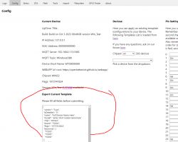
    Yes, that's what we use for devices list:
    Screenshot of a device configuration panel interface with a template export section.
    Helpful post? Buy me a coffee.
  • #11 20756665
    drkbg
    Level 4  
    There you go (I filled out some of the fields that were missing):

    {
      "vendor": "Tuya",
      "bDetailed": "0",
      "name": "WD-01ADE Tuya water pump with WiFi",
      "model": "WD-01ADE",
      "chip": "BK7231N",
      "board": "CBU",
      "flags": "1024",
      "keywords": [
        "garden",
        "JOEKOL",
        "Irrigation"
      ],
      "pins": {
        "7": "Btn_n;2",
        "8": "Btn_n;1",
        "14": "Rel;2",
        "16": "Rel;1",
        "20": "WifiLED;0"
      },
      "command": "",
      "image": "https://obrazki.elektroda.pl/5341773600_1686167391.jpg",
      "wiki": "https://www.elektroda.com/rtvforum/topic3982582.html"
    }

    Not sure what the board is meant to be but most probably in that case the answer would be CBU-NL.

    I would suggest joining the two threads about this device https://www.elektroda.com/rtvforum/topic3982582.html and this one here.


    One more question about this device that I cannot find the answer in the forum:

    Buttons work, but you have to push them twice. I checked the logs (which are very talkative writing):
    
    Info:GEN:7 Button_OnLongPressHold
    Info:GEN:8 Button_OnLongPressHold
    Info:GEN:7 Button_OnLongPressHold
    Info:MAIN:Time 471, idle 183206/s, free 71880, MQTT 1(2), bWifi 1, secondsWithNoPing 1, socks 2/38 
    Info:GEN:8 Button_OnLongPressHold
    Info:GEN:7 Button_OnLongPressHold
    Info:GEN:8 Button_OnLongPressHold
    Info:GEN:7 Button_OnLongPressHold
    Info:GEN:8 Button_OnInitialPressDown
    Info:MAIN:Time 472, idle 198358/s, free 71880, MQTT 1(2), bWifi 1, secondsWithNoPing 1, socks 2/38 
    Info:GEN:7 Button_OnLongPressHold
    Info:GEN:7 Button_OnLongPressHold
    Info:GEN:8 Button_OnLongPressHoldStart
    Info:MAIN:Time 473, idle 190853/s, free 71880, MQTT 1(2), bWifi 1, secondsWithNoPing 1, socks 2/38 
    Info:GEN:7 Button_OnLongPressHold
    Info:GEN:8 Button_OnLongPressHold
    Info:GEN:7 Button_OnLongPressHold
    Info:GEN:8 Button_OnLongPressHold
    Info:MAIN:Time 474, idle 189577/s, free 71880, MQTT 1(2), bWifi 1, secondsWithNoPing 1, socks 2/38 
    Info:GEN:7 Button_OnLongPressHold
    Info:GEN:8 Button_OnLongPressHold
    Info:GEN:7 Button_OnLongPressHold
    Info:GEN:8 Button_OnLongPressHold
    Info:MAIN:Time 475, idle 191014/s, free 71880, MQTT 1(2), bWifi 1, secondsWithNoPing 1, socks 2/38 
    

    I believe the first push of the button is the
    Button_OnInitialPressDown
    and the second is
    Button_OnLongPressHoldStart

    1. Is it possible to use the Button_OnInitialPressDown event to start the pump?
    2. Why is this Button_OnLongPressHold constantly coming in the logs?
  • #12 20756732
    p.kaczmarek2
    Moderator Smart Home
    Why are you using Btn_n instead of Btn? Btn_n has inversed logic, and you most likely have just normal Buttons, so code thinks that Button is pressed all the time when it's not pressed in reality, that's why you get Button_OnLongPressHold spam..
    Helpful post? Buy me a coffee.
  • ADVERTISEMENT
  • #13 20756809
    drkbg
    Level 4  

    That is a good question. Andy41 also asked the same one in the other thread.

    I guess this happens when you just copy paste stuff from the internet :)

    Will try without the _n and report.
  • #14 20756838
    p.kaczmarek2
    Moderator Smart Home
    So you haven't used our automatic GPIO extraction?


    Helpful post? Buy me a coffee.
  • #15 20757004
    drkbg
    Level 4  
    The one above doesn't work very well for me:

    When I use the "Extract Config from Tuya Binary" I get the following JSON:

    
    {
    	"abi": "0",
    	"id": "null",
    	"swv": "1.1.8",
    	"bv": "40.00",
    	"pv": "2.2",
    	"lpv": "3.4",
    	"pk": "key4rj5r4pv5wgwp",
    	"firmk": "null",
    	"cadv": "1.0.5",
    	"cdv": "1.0.0",
    	"dev_swv": "1.1.8",
    	"s_id": "null",
    	"dtp": "0",
    	"sync": "0",
    	"attr_num": "1",
    	"mst_tp_0": "9",
    	"mst_ver_0": "1.1.8",
    	"mst_md5_0": "null",
    	"mst_tp_1": "0",
    	"mst_ver_1": "null",
    	"mst_md5_1": "null",
    	"mst_tp_2": "0",
    	"mst_ver_2": "null",
    	"mst_md5_2": "null",
    	"mst_tp_3": "0",
    	"mst_ver_3": "null",
    	"mst_md5_3": "null }0EAtls_ca_cnt0)!Agw_wsm{nc_tp",
    	"ssid": "null",
    	"passwd": "null",
    	"md": "0",
    	"random": "0",
    	"wfb64": "1",
    	"stat": "0",
    	"token": "null",
    	"region": "null",
    	"reg_key": "null",
    	"dns_prio": "03Awf_start_md3uuid",
    	"psk_key": "blabla",
    	"auth_key": "blabla",
    	"ap_s{nc_tp": "1",
    	"ap_ssid": "SmartLife",
    	"ap_passwd": "null",
    	"country_code": "CN",
    	"bt_mac": "null",
    	"bt_hid": "null",
    	"prod_test": "false",
    	"fac_pin": "blabla",
    	"lckey": "null",
    	"h_url": "null",
    	"h_ip": "null",
    	"hs_url": "null",
    	"hs_ip": "null",
    	"hs_psk": "null",
    	"hs_psk_ip": "null",
    	"mqs_url": "null",
    	"mqs_ip": "null",
    	"mq_url": "null",
    	"mq_ip": "null",
    	"ai_sp": "null",
    	"ai_sp_ip": "null",
    	"mq_psk": "null",
    	"mq_psk_ip": "null",
    	"lp_url": "null",
    	"lp_ip": "null",
    	"time_z": "null",
    	"s_time_z": "null",
    	"wx_app_id": "null",
    	"wx_uuid": "null",
    	"dy_tls_m": "0",
    	"cloud_cap": "0",
    	"psk21_key": "null }eA000004sa7s[{type",
    	"mode": "rw",
    	"property": "{type",
    	"{type": "obj",
    	"{mode": "rw",
    	"type": "raw}",
    	"max": "86400",
    	"scale": "0",
    	"step": "1",
    	"maxlen": "255}",
    	"index": "0}{nc_tp",
    	"cnt": "0}EGAastro_timer{timestamp"
    }


    and the following text description:

    
    Sorry, no meaningful pins data found. This device may be TuyaMCU or a custom one with no Tuya config data.
    No module information found.
    And the Tuya section starts at UNCOMMON POSITION 0


    This results in following generated script in the WebApp:

    
    ClearIO // clear old GPIO/channels
    lfs_format // clear LFS
    StartupCommand ""  // clear STARTUP
    stopDriver *  // kill drivers


    I am pretty sure this is not what is expected.. so what is wrong?
  • #16 20757008
    p.kaczmarek2
    Moderator Smart Home
    Ah okay, this device is a custom one which has a hardcoded behaviour, there are no pins in JSON
    Helpful post? Buy me a coffee.

Topic summary

The discussion revolves around flashing firmware onto the WD-01ADE Tuya water pump, which utilizes the BK7231N chip. The user encounters issues during the flashing process, specifically with the blue diode's behavior and the requirement to shorten GND and CEN. Responses suggest using an external power supply, such as an AMS1117-3.3V, instead of relying solely on the CH340's 3.3V output, as the latter may not provide sufficient current. The successful flashing procedure involves connecting the CH340G to the device, powering it via USB, and properly managing the GND and CEN connections. Additionally, the user shares their configuration for Home Assistant, noting issues with button logic that may stem from using incorrect GPIO settings.
Summary generated by the language model.
ADVERTISEMENT