logo elektroda
logo elektroda
X
logo elektroda

Flashing New Tongou TO-Q-SY1-JWT Device: DIN Rail Switch and Meter, BK7231 template script

VIDPRO 19392 82
ADVERTISEMENT
  • ADVERTISEMENT
  • #62 21285189
    dwmw2
    Level 6  
    luxmcdiver wrote:
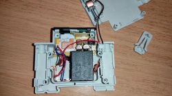
    Hi, I have a TO-Q-SY2-JWT which has a shunt-resistor instead of the coil. Has anybody flashed such a device?
    Yes, I have flashed a bunch of these, and they're mostly indistinguishable in software from the ones with a coil. Even the calibration parameters are in the same range.
  • #63 21294869
    leśny_ziutek
    Level 12  
    From the manufacturer's information it appears that the SY2 differs from the SY1 not only in the use of a shunt instead of a transformer, but also in the additional function of overcurrent and overvoltage protection (Over and Under Voltage Protection).
  • #64 21294989
    luxmcdiver
    Level 3  
    Does anybody know how to configure these additional SY2 protections in openbeken?
  • #65 21297732
    p.kaczmarek2
    Moderator Smart Home
    How this device looks like? Which chip is used inside?

    Are the protections you mention handled by WiFi module, or are they implemented outside it? I don't think it's possible to make a reliable, quick protection in the WiFi module code... but if you don't need it to react quickly, then you can just script OBK to turn off relay when current exceeds given value.
    Helpful post? Buy me a coffee.
  • ADVERTISEMENT
  • #66 21297841
    luxmcdiver
    Level 3  
    It looks same as the SY1 and uses the BK7231N & BL0942.
  • #67 21297851
    p.kaczmarek2
    Moderator Smart Home
    So Tuya does their protections in the software?
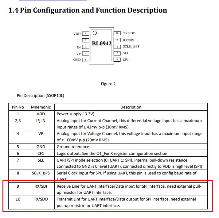
    Pin configuration diagram of the BL0942 chip with a description of each pin function.
    BL0942 just sends data via UART (or SPI) to WiFi module and WiFi module can process it once it's received.
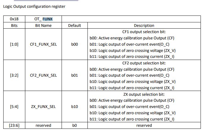
    EDIT: I edited out incorrect information, it seems that BL0942 has actually ability to detect overcurrent/overvoltage via FUNX register and signal it on CF1/CF2/ etc pins.

    If you don't need to react very fast, you can use obk autoexec.bat script:
    
    addChangeHandler Voltage > 251 POWER OFF
    

    etc, etc...
    Helpful post? Buy me a coffee.
  • #68 21300319
    leśny_ziutek
    Level 12  
    It seems you can configure the BL0941 V1.06 CF1 output (also CF2, ZX otputs in bigger packages) to signal the over current condition (see OT_ FUNX) register. Is this signal connected anywhere? I can't check this myself for now, but two SY2 are on their way to me so will check when they arrive. The manufacturer clearly distinguishes SY2 from SY1, specifying the protection capability of SY2 as the only difference. But it may actually be poorly and unreliably implemented using the logic executed by the WiFi module as @p.kaczmarek2 said.
  • #69 21300797
    p.kaczmarek2
    Moderator Smart Home
    I see, I wasn't aware that CF1 can be configured in that way.
    Logic output configuration register table with options for CF1, CF2, and ZX.
    If CF1 (etc) are connected somewhere, then maybe we indeed just need to configure OT_Funx register and the circuit will do the rest.
    Helpful post? Buy me a coffee.
  • #70 21301079
    luxmcdiver
    Level 3  
    It would be nice to have the BL0942 Current fast RMS threshold in the Web application /Tools / Power Metering section, as well as a command box to activate the overcurrent protection.
    Is that feasable?
  • ADVERTISEMENT
  • #71 21301610
    leśny_ziutek
    Level 12  
    Only if CF1 is used in the SY2 for this purpose.
  • #72 21305819
    p.kaczmarek2
    Moderator Smart Home
    OpenBeken already has mechanism to write to BL0942 registers so it should be possible to enable it if used hardware has CF pin available:
    Code: C / C++
    Log in, to see the code
    Helpful post? Buy me a coffee.
  • #73 21390816
    max_mcu
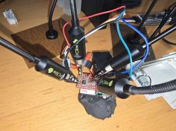
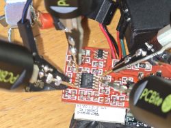
    Level 3  
    Hello community, I have the following problem: The relay is a bi stable relay. When the power is lost and then switched back on, the switch + LED is not on if the relay was switched on before the power failure. How can I determine after the power failure whether the relay is still on or off? Can this be fixed in the software?
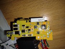
  • #74 21401656
    Drapol13
    Level 1  
    Hi,
    I'm really struggling to load up this firmware. I tried BK7231GUIFlashTool-v5.
    I wanted to read firmware first. I tried disconnecting GND and also connecting CEN to GND for a fraction of a second.
    I keep getting this counter...
    Read parms: start 0x00 (sector 0), len 0x200000 (0 sectors)
    Now is: poniedziałek, 20 stycznia 2025 16:07:49.
    Flasher mode: BK7231T
    Going to open port: COM4.
    Serial port open!
    Getting bus... (now, please do reboot by CEN or by power off/on)
    Getting bus failed, will try again - 0/100!
    Getting bus failed, will try again - 1/100!
    Getting bus failed, will try again - 2/100!
    Getting bus failed, will try again - 3/100!

    I also tried to load up ESPhome but I also can't connect. Tried swapping RX TX nothing helped.
    Connections are good.

    Electronic circuit connected to several PC Bite test probes on a wooden table.
    Close-up of a PCB connected with probes.
  • #75 21402384
    p.kaczmarek2
    Moderator Smart Home
    max_mcu wrote:
    Hello community, I have the following problem: The relay is a bi stable relay. When the power is lost and then switched back on, the switch + LED is not on if the relay was switched on before the power failure. How can I determine after the power failure whether the relay is still on or off? Can this be fixed in the software?

    Well, maybe it would be enough to just set startup value of relay channel to -1, so OpenBeken remember it between reboots?

    @Drapol13 There can be multiple issues at play:
    - too long wires, poor contacts
    - BL0942 or something may be blocking UART, I'm not sure, but I remember that it also worked for me several times with BL0942
    - you need to have a good 3.3V power supply, directly from USB to UART won't work
    - maybe you need to try other baud or other USB to UART converter
    Helpful post? Buy me a coffee.
  • #76 21487925
    leśny_ziutek
    Level 12  
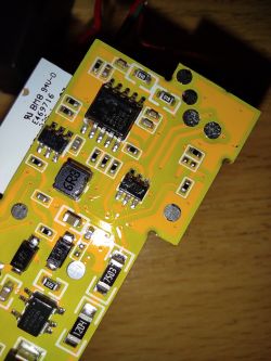
    I've managed to open and flash the SY2 version:

    Opened casing with visible electronics and connected wires.
    Close-up of a yellow PCB with visible electronic components, including an MD7620A integrated circuit.
    Close-up of a circuit board with visible electronic components and the marking 6R3.

    Also checked the connections on the board with a multimeter. The relay is connected to the MD7620A driver. Both inputs of the driver are directly connected to the CBU (P24, P26). The BL0942 CF1 pin seems to be left floating. In case of any autonomous control of the relay by BL0942 it should be some circuity on the board connected to the CF1 and MD7620A but the direct connection between MD7620A and CBU indicates that nothing of this sort is implemented.
  • ADVERTISEMENT
  • #77 21556224
    casiopeia80
    Level 2  
    Hello everyone!
    Many thanks for the firmware — great work!
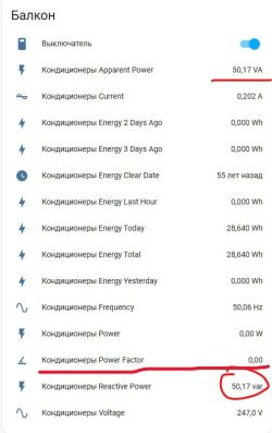
    However, I've encountered one issue. After flashing, the module doesn't seem to take the power factor into account in its calculations.
    I've been using this smart switch with the stock firmware for about a year. It powers three air conditioners, and I’m absolutely sure the original firmware correctly factored in cos(φ) (power factor) when calculating the reactive component of the AC current.
    For example, in standby mode, the three air conditioners consumed around 10 watts on the original firmware. With the new firmware, I’m seeing standby values of around 56 watts, which I believe is because the power factor isn’t being considered.
    Could this be improved in future updates?
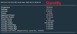
    Energy monitoring panel for balcony air conditioners, highlighting apparent power 50.17 VA and reactive power 50.17 var.
  • #78 21556241
    p.kaczmarek2
    Moderator Smart Home
    Welcome to forum! Just to confirm, you're using this device from this topic, with BL0942 connected via SPI?

    Added after 41 [seconds]:

    Also, did you calibrate this device after flashing with VoltageSet, PowerSet and CurrentSet commands?
    Helpful post? Buy me a coffee.
  • #79 21556434
    casiopeia80
    Level 2  
    >>21556241
    Yes, I am using the TO-Q-SY2-JWT device model.
    I realized that I needed to enable Flag 25 – [POWER] Allow negative current/power for power measurement (all chips, BL0937, BL0942, etc) in the device settings.

    I’ve read about the calibration process in the web interface, but I couldn’t understand how the power factor can be properly calibrated using a purely resistive load like an incandescent bulb.

    So, I decided to try a different approach.
    In my apartment, I have three LG air conditioners connected through this TO-Q-SY2-JWT module. Back when the device was running the original firmware, I monitored its readings and noticed that, in standby mode, the total power consumption was shown as around 10 watts. The line voltage was about 235 volts, and the current draw was 400 mA (with cos(φ) close to maximum in this low-power mode).

    At the time, I also measured the current using a True RMS multimeter — the readings matched the module’s output.
    So I tried calibrating your firmware using the same conditions: I set the air conditioners to standby and entered those known values into the calibration fields in the web interface.

    Now, the readings seem quite accurate — both when the air conditioners are in standby mode and when they are running. The measured values closely match the power consumption reported by the air conditioners themselves on their built-in displays.

    I have one more question: is there any way to extract the calibration data from the original firmware?

    Screen showing electric power consumption measurements and StandBy status.

    Screen displaying electrical energy measurement data with a red Power on message.
  • #80 21556477
    przemsi_ele
    Level 11  
    >>21556434
    yes u can extract original calibration setup, there is post about that , but i always calibrate using classic bulb, it is olmost true resistance , in my cases it is always satisfy

    https://esphome.io/components/sensor/bl0942.html

    maybe this will be halpfull for you
  • #81 21556582
    sq3evp
    Level 37  
    przemsi_ele wrote:
    >>21556434 .
    yes, you can extract the original calibration configuration, there is a post on this topic, but I always calibrate with a classic bulb, it is almost the true resistance, in my cases it is always satisfactory

    Not really - a cold fibre has a different resistance to a heated one. I guess the heater is a more linear element or high power resistor.
  • #82 21556630
    casiopeia80
    Level 2  
    >>21556477 Thanks! I found an old 60W incandescent bulb (with a filament) in storage. I used it for calibration. The readings turned out to be about the same as when I calibrated using the air conditioners. :) At first, I didn’t realize that during this type of calibration, a power factor of 1 is assumed by simply using the measured power value as the product of voltage and current (U × I).
  • #83 21559062
    anatolyshokalo
    Level 1  
    >>20663233 Can you please show what pins did you used for flashing? Thanks

Topic summary

The discussion revolves around flashing the Tongou TO-Q-SY1-JWT device, a DIN rail switch and meter utilizing the BK7231N chip. Users share their experiences with flashing the device using various methods, including serial flashing and Tuya CloudCutter, while addressing issues related to relay functionality, power state retention, and configuration challenges. Several users report successful flashing and integration with Home Assistant (HA), while others encounter difficulties with firmware versions and device behavior post-flashing. The conversation also touches on calibration data, pin configurations, and the differences between hardware versions. Users provide insights into troubleshooting, including the importance of correct wiring and the potential for overheating in flashed devices.
Summary generated by the language model.
ADVERTISEMENT