logo elektroda
logo elektroda
X
logo elektroda

Flashing New Tongou TO-Q-SY1-JWT Device: DIN Rail Switch and Meter, BK7231 template script

VIDPRO 19392 82
ADVERTISEMENT
  • #31 20974510
    p.kaczmarek2
    Moderator Smart Home
    @yorainoy excuse, what do you mean by frequency inside?

    @Spag cloudcutter is not a reliable solution due to many devices patched, we suggest using the UART flashing method, see tutorials playlist here:
    https://www.youtube.com/playlist?list=PLzbXEc2ebpH0CZDbczAXT94BuSGrd_GoM
    Helpful post? Buy me a coffee.
  • ADVERTISEMENT
  • #32 20974860
    Spag
    Level 3  
    @p.kaczmarek2 Thank you, I was able to flash it via UART and it's working perfectly now - I was just hoping I could flash it without having to destroy the rivets to open the case..

    Congratulations on an amazing piece of software!

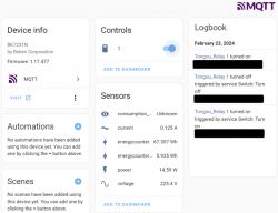
    Screenshot of an MQTT interface displaying device info for BK7231N, controls, sensors, and logs.
  • ADVERTISEMENT
  • #33 20974871
    p.kaczmarek2
    Moderator Smart Home
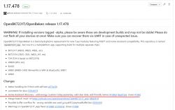
    Thanks, by the way, I think you'd benefit from updating to the new release:
    Screenshot of OpenBK7231T/OpenBeken release 1.17.478 listing changes and developer version warnings.
    Especially thanks to this commit:
    
    Home Assistant discovery - add energy counters today/yesterday, add clear date, add friendly names (#1092) (8eaf72e), closes #1092
    
    Helpful post? Buy me a coffee.
  • #34 20974872
    babaganesh
    Level 3  
    >>20663233

    What was the easy way to open it up ?
  • #35 20974921
    Spag
    Level 3  
    @p.kaczmarek2 Fantastic, perfect timing! :)

    @babaganesh You have to drill the rivets to destroy them... only then you can open the case.
  • #36 21080140
    onkel11
    Level 5  
    Hi,

    any idea how do seal th device after flashing ?
    Somewhere to buy the seal pins ?
  • #38 21080758
    onkel11
    Level 5  
    thanks

    Edit:

    I found another solution and will test it:

    Aderendhülsen unisoliert, Nennquerschnitt 1,50qmm, Länge 18mm, Außendurchmesser 2,00 mm

    the original ones do also have almost the same size.

    Keep you informed.

    Update:

    So this worked perfectly:
    hxxxs://www.amazon.de/Aderendh%C3%BClsen-Crimpverbinder-unisoliert-Kunststoffkragen-Nennquerschnitt/dp/B08QS2KR49?source=ps-sl-shoppingads-lpcontext&ref_=fplfs&smid=AER43YRX1AHYK&th=1

    Best regards
  • #39 21110271
    firsoff091
    Level 1  
    Hello,

    We purchased a smart WiFi switch, Tongou TO-Q-SY1-JWT, and flashed it with OpenBeken following your instructions. Thank you for the guidance.

    The device has been working for over a month, collecting metrics and being controlled via Home Assistant (HA). However, we've encountered an issue where the switch turns off the electricity without any apparent reason. This has happened twice, with a one-week interval between occurrences. Unfortunately, we couldn't determine the cause of the "failure" based on the collected metrics in HA. The graphs of the collected metrics show everything within normal ranges.

    Question:
    How can we configure the device to save all logs to a file or any other storage? It would be helpful to retain logs for at least a few hours, so that in case the issue recurs, we can "download or open the file" and analyze it in detail to understand the cause of the power off.

    Thank you in advance for your assistance!
  • ADVERTISEMENT
  • #40 21118531
    silvestro_gatto
    Level 7  
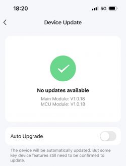
    TO-Q-SY1-JWT 32A Smart WiFi Switch With Metering Function
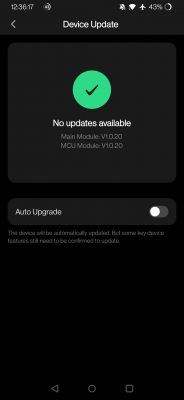
    Tuya Main Module Firmware V1.0.18 (not supported by Tuya CloudCutter)
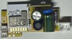
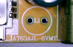
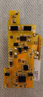
    Yellow PCB version AT63AJL-8VMT

    Device update screen showing no updates available.
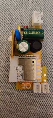
    Yellow printed circuit board of a smart WiFi switch with electronic components. Close-up of a yellow printed circuit board labeled AT63AJL-8VMT.

    Flashed with OpenBK7231N build version 1.17.612 and configured with the following OBK template

    
      "pins": {
        "9": "LED_n;1",
        "15": "WifiLED_n;0",
        "17": "Btn;1",
        "24": "BridgeFWD;1",
        "26": "BridgeREV;1"
      },
    
      "command": "backlog startDriver BL0942; startDriver NTP"
    

    everything is working fine but the button, when pressed, does not switch on/off

    GPIO Doctor is showing P17 Val changing Low/High only when dInput is selected.

    Any advice? Thank you!

    Added after 10 [hours] 4 [minutes]:

    I found the solution to my problem with the unresponsive button ...

    Flag 41 [BTN] Ignore all button events (aka child lock) in Configure General/Flags was checked by default.

    Screenshot of flag settings in OpenBK7231N software.

    After unchecking the flag, the button started working as expected.
  • #41 21163281
    Wobbie
    Level 3  
    Hello all and a big thanks to all that contribute here especially the moderator @p.kaczmarek2 Great Job!

    I am having difficulty flashing this device Tongou TO-Q-SY1_163JWT 63 Amp Version breaker Electronic module on a denim fabric background. The image shows a circuit board of a Tongou TO-Q-SY1_163JWT 63 Amp device. . I am familiar with the process and have successfully flashed other switch devices eg: [BK7231N] Aubess Mini Switch 16A.

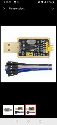
    I use a USB / TTL serial device from China CH430G-2 which has worked well in the past plus I swapped it out with a spare to confirm functionality.

    I am using the latest flasher bk7231flasher_1.3.3

    Attempts at flashing in place were unsuccessful so I decided to remove the CBU from the main board but still unsuccessful! Resetting the module by earthing CEN does not start the flash sequence (have tried many times). Also trying another 3.3 v power source, swapping rx1 and tx1 on uart1 just in case but to no avail!

    Attaching it to Tuya Smart app all works OK, noticing the firmware is V 1.0.20. Is it possible that Tuya have disabled flashing (bootloader rom) somehow? I do notice on their web site "Flash and Authorize CB Modules"
    https://developer.tuya.com/en/docs/iot/CB-series-module?id=Kbruyciad6154


    Any tips or advice appreciated
    R Screenshot of device update showing version V1.0.20. USB to TTL connector with programming cables.
  • #42 21173683
    silvestro_gatto
    Level 7  
    >>21163281

    Hi @Wobbie,
    actually flashing my device (TO-Q-SY1-JWT 32A Smart WiFi Switch With Metering Function - Tuya Firmware V1.0.18 - PCB marking AT63AJL-8VMT) was quite straightforward.

    I checked my notes and I did not find any specific issue with this device.

    I used a cheap CP210x USB to TTL UART Serial Convertor Module (set at 3.3V Voltage Level) and short wires connected to the CBU module, without removing it from the main board.

    This is the CBU module pinout:
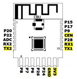
    Pinout diagram of CBU module with highlighted pins TX2, RX1, TX1, CEN, 3V3, and GND.

    I used 3.3V, GND, and TX2 to capture the log from factory firmware, then I connected 3.3V, GND, TX1 and RX1 to backup factory firmware and upload OpenBK7231N build version 1.17.612, using BK7231 Easy UART Flasher (Set chip type: BK7231N - Set baud rate: 921600)

    As you wrote, CEN pin has to be shorted to GND to reboot, when BK7231Flasher.exe is "getting the bus ...."

    see the line " Getting bus... (now, please do reboot by CEN or by power off/on)" in the below log from flasher

    
    Backup name is set to din2.
    Starting read backup and flash new!
    Now is: Wednesday, June 12, 2024 6:03:47 PM.
    Flasher mode: BK7231N
    Going to open port: COM10.
    Serial port open!
    Getting bus... (now, please do reboot by CEN or by power off/on)
    Getting bus success!
    Going to set baud rate setting (921600)!
    Will try to read device flash MID (for unprotect N):
    Flash MID loaded: 1560EB
    Will now search for Flash def in out database...
    Flash def found! For: 1560EB
    Flash information: mid: 1560EB, icName: TH25Q_16HB, manufacturer: TH, szMem: 1000000, szSR: 2, cwUnp: 0, cwEnp: 7, cwMsk: 407C, sb: 2, lb: 5, cwdRd: 05-35-FF-FF, cwdWr: 01-FF-FF-FF
    Entering SetProtectState(True)...
    sr: 34
    sr: 34
    final sr: 34
    msk: 407c
    cw: 0, sb: 2, lb: 5
    bfd: 0
    sr: 0
    sr: 0
    final sr: 0
    msk: 407c
    cw: 0, sb: 2, lb: 5
    bfd: 0
    SetProtectState(True) success!
    Going to start reading at offset 0x00...
    Reading 0x00... Ok!
    ......


    Let me know if you need any further detail or clarification and good luck with your flashing!
  • #43 21179078
    Wobbie
    Level 3  
    Thanks @silvestro_gatto
    Found my problem; RX connection got broken going into the CBU when removing from main board (not enough flux I think)! Managed to fix it so happy ending.
  • #44 21179280
    silvestro_gatto
    Level 7  
    >>21179078

    @Wobbie, I am glad you found the problem and cut the device off from the cloud. Ace!
    Cheers
  • #46 21188194
    dwmw2
    Level 6  
    Not able to test fully, as the power supply in this unit is broken so I can only power the CBU from +3.3v and can't test the relay. But I think this should mostly work as an esphome config. I haven't yet worked out what to do about restoring the original state on reboot, so I'm just forcing it on. It isn't a circuit breaker, and should never be used as a safety device, so I guess that's OK.
    Code: YAML
    Log in, to see the code


    Added after 8 [hours] 19 [minutes]:

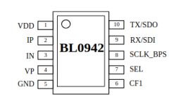
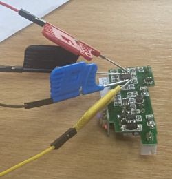
    All the pins needed for flashing this are on the BL0942 on the back of the board, easy to grab with SOIC probes.
    Block diagram of the BL0942 integrated circuit with labeled pins.

    Note that TX and RX are labelled for the BL0942, so they route to the RX1 and TX1 pins on the CBU respectively. I'm tempted to try drilling a tiny hole in the side of the next unit and doing keyhole surgery instead of drilling out the rivets and taking it completely apart.

    Printed circuit board with attached test probes.
  • #48 21190981
    divadiow
    Level 34  
    Does this mean something in OpenBeken regarding BL0942 can/should be adjusted?
  • #49 21191153
    dwmw2
    Level 6  
    >>21190981
    divadiow wrote:
    Does this mean something in OpenBeken regarding BL0942 can/should be adjusted?


    The short answer is 'yes'. The more helpful answer I'm still working out the final details, but it's basically there in the ESPHome issue I linked. We *can* get the vref/iref/pref/eref values out of the Tuya firmware, and we can also calculate the pref/eref values from vref/iref which can be determined empirically.
  • #51 21197592
    dwmw2
    Level 6  
    Note: Do NOT be tempted to wire one of these units up 'backwards' to calibrate it, with the feed coming in via the load terminals and the load connected to the feed terminals.

    I thought that would work as long as the relay was already turned on, and that it would include the power drawn by the unit itself in the measurement, so it was perfectly comparable with the external measurement.

    Now my relay doesn't seem to work any more. It clicks but there's never any connection.
  • #53 21208313
    divadiow
    Level 34  
    That's exciting. Do you plan a similar PR for OpenBeken/Easy UART Flasher tool?

    Also makes me wonder if the ADC 2400 multiplier can be extracted from battery device firmware. The same I guess for temp/humidity sensors too.
  • #54 21263275
    erikwouterson
    Level 3  
    Hi all,
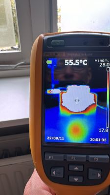
    Successfully flashed a few TO-Q-SY2-JWT, only thing I noticed that of the flashed devices the coils are getting hot, 55 degrees Celsius even without load, original software remains cold.

    Anyone else encountered this issue?
    Thanks
    Erik

    Fluke thermal imager displaying a temperature of 55.5°C.
  • #55 21263433
    dwmw2
    Level 6  
    >>21263275 Are you driving the 'bridge' with pulses instead of holding the line high?
  • #56 21264753
    erikwouterson
    Level 3  
    >>21263433 hi, can you please explain how I would be able to tell the difference?
    Thanks
    Erik
  • #57 21265055
    dwmw2
    Level 6  
    >>21264753
    Quote:
    can you please explain how I would be able to tell the difference?


    If you're using OBK, see the discussion about `Rel` vs. `BridgeFwd` at https://www.elektroda.com/rtvforum/topic3934580-30.html

    If you're using ESPHome, see https://devices.esphome.io/devices/Tongou-TO-Q-SY1-JWT (and I've got an actual bridge driver in https://github.com/esphome/esphome/pull/7421 which might one day get merged, to make that a bit easier).

    (Even if you're not using ESPHome, read the part about calibration in that one).
  • #58 21265333
    erikwouterson
    Level 3  
    >>21265055 Thanks for this, I might need to dust of my oscilloscope:-), and I will test weekend or early next week
  • ADVERTISEMENT
  • #59 21282208
    luxmcdiver
    Level 3  
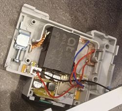
    Hi, I have a TO-Q-SY2-JWT which has a shunt-resistor instead of the coil. Has anybody flashed such a device? Open TO-Q-SY2-JWT device with a visible shunt resistor instead of a coil.
  • #60 21282253
    p.kaczmarek2
    Moderator Smart Home
    I think it should be easily flashable. It does not matter whether it's a coil or resistor. All that matters is which IC is doing measurement. We have BL0942, BL0937, and CSE support...
    WiFi module does not do the measurement directly.
    Helpful post? Buy me a coffee.

Topic summary

The discussion revolves around flashing the Tongou TO-Q-SY1-JWT device, a DIN rail switch and meter utilizing the BK7231N chip. Users share their experiences with flashing the device using various methods, including serial flashing and Tuya CloudCutter, while addressing issues related to relay functionality, power state retention, and configuration challenges. Several users report successful flashing and integration with Home Assistant (HA), while others encounter difficulties with firmware versions and device behavior post-flashing. The conversation also touches on calibration data, pin configurations, and the differences between hardware versions. Users provide insights into troubleshooting, including the importance of correct wiring and the potential for overheating in flashed devices.
Summary generated by the language model.
ADVERTISEMENT