logo elektroda
logo elektroda
X
logo elektroda

Flashing Connex Connect CC-P2000 10A Smart WiFi Switch with WB2S: A User's Journey

rudolfbyker 3294 34
ADVERTISEMENT
  • #31 20699250
    rudolfbyker
    Level 4  

    The journey continues with the next 7 switches. I'm stubbornly trying to figure out how to flash them without desoldering, to save time. With the shorter wiring, I'm getting a tiny bit further than before. When I press the CEN button, it immediately says "Getting bus success!", but then hangs at "Reading 0x00". (Exactly the same if I do a power cycle.) When I check with my oscilloscope, I can see that the chip is replying with some data, and then goes silent. My oscilloscope is not good enough to allow me to check what is actually being sent/received both ways.

    Is there a way in software to monitor what is being sent/received as text?

    If not, I could buy two more USB-UART devices and connect one RX line of each to the TX-RX and RX-TX lines of the programming setup, just to monitor what is going both ways.

    Added after 17 [minutes]:

    I can create an intercepted UART using this command from https://unix.stackexchange.com/a/225904/28063
    socat /dev/ttyUSB0,raw,echo=0 SYSTEM:'tee in.txt | socat - "PTY,link=/tmp/ttyV0,raw,echo=0,waitslave" | tee out.txt'

    and then monitor it with
    tail -f in.txt
    in one terminal and
    tail -f in.txt
    in another terminal.

    But I can't set the flasher to use /tmp/ttyV0.
  • ADVERTISEMENT
  • #32 20699262
    p.kaczmarek2
    Moderator Smart Home
    Let's try another approach.

    Connect GND, RX, TX and then also connect 5V to the input of the onboard 3.3V regulator, so it outputs correct 3.3V for WiFi module.

    Then try resetting with power off and on.
    Helpful post? Buy me a coffee.
  • ADVERTISEMENT
  • #33 20699326
    rudolfbyker
    Level 4  
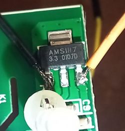
    OK, so that is the AMS1117 3.3V chip. Datasheet: http://www.advanced-monolithic.com/pdf/ds1117.pdf

    Close-up of an AMS1117 3.3V chip mounted on a PCB with attached wires.

    I get the same results when powering from the 5V pin, except that now the relay and LED are also on (as expected). I tested with CEN and with power cycle. I tested with USB 5V and with bench power supply (with very short wires). It hangs at "Reading 0x00".

    If I wait long enough, I get this:
    failed with serial.BytesToRead 4095 (expected 4111)
    The beginning of buffer in UART contains 040EFF01E0FCF4061009000000200043 data.
    Failed! There was no result to save.


    I'm also monitoring the 5V line with my oscilloscope, and it's not dropping, even by a µV, so it can't be a power supply issue.
  • ADVERTISEMENT
  • #34 20699383
    p.kaczmarek2
    Moderator Smart Home
    Does the same happen with hid_download_py Python tool? I had some reports saying that our GUI tool is less stable when run on Mono on non-Windows platform
    Helpful post? Buy me a coffee.
  • #35 20699478
    rudolfbyker
    Level 4  

    The Python flasher works in-circuit on Linux! Yay!

    Full steps for someone trying to replicate this:
    - Download the latest hid_download_py from GitHub here: https://github.com/OpenBekenIOT/hid_download_py
    - Extract it somewhere and cd into it.
    - Create a venv inside of it:
    python -m venv

    - Activate the venv:
    . venv/bin/activate

    - Install dependencies in the venv:
    pip install -r requirements.txt

    - Download the latest firmware from GitHub here: https://github.com/openshwprojects/OpenBK7231T_App/releases Make sure you get the "BK7231T UART Flash" version, e.g., "OpenBK7231T_UA_1.17.221.bin".
    - Run the flasher:
    ./uartprogram OpenBK7231T_UA_1.17.221.bin -w

    - Cycle power or press CEN button (i.e. connect CEN to GND momentarily)

    I tried reading/writing the OBK config using the GUI tool AFTER flashing successfully with `hid_download_py`, but it still fails with the same problem.

    I dual-boot Windows 10 and Linux Mint, but I can't get my USB-UART to work reliably on Windows (always getting errors about permissions or not being able to open the port). On Linux, it seems to work well.

    I also tried in a Windows 10 VirtualBox running on top of my Linux Mint, sharing the USB-UART device from Linux to the VM. I get the exact same errors as on the bare-metal Windows. So I'm highly suspecting that the problem is with the Windows 10 driver for my very old USB-UART converter!

    Starting read!
    Now is: Saturday, 19 August 2023 11:29:15 AM.
    Flasher mode: BK7231T
    Going to open port: COM3.
    Serial port open exception: System.IO.IOException: A device which does not exist was specified.
       at System.IO.Ports.InternalResources.WinIOError(Int32 errorCode, String str)
       at System.IO.Ports.SerialStream..ctor(String portName, Int32 baudRate, Parity parity, Int32 dataBits, StopBits stopBits, Int32 readTimeout, Int32 writeTimeout, Handshake handshake, Boolean dtrEnable, Boolean rtsEnable, Boolean discardNull, Byte parityReplace)
       at System.IO.Ports.SerialPort.Open()
       at BK7231Flasher.BK7231Flasher.openPort() in W:GITBK7231GUIFlashToolBK7231FlasherBK7231Flasher.cs:line 95
    Failed to open serial port!
    OBK config load failed.

Topic summary

The discussion revolves around the flashing process of the Connex Connect CC-P2000 10A Smart WiFi Switch, which contains a WB2S module. The user initially faced challenges with wiring, UART connections, and firmware flashing. After troubleshooting, including using a USB-UART converter and examining the PCB, the user successfully extracted the device configuration and flashed the firmware using the hid_download_py tool on Linux. The device was eventually connected to WiFi after correcting the SSID issue. The user also configured additional features, such as a digital input for a toggle switch, and shared insights on the device's pin mapping and safety considerations regarding its non-isolated power supply.
Summary generated by the language model.
ADVERTISEMENT