logo elektroda
logo elektroda
X
logo elektroda

Flashing Connex Connect CC-P2000 10A Smart WiFi Switch with WB2S: A User's Journey

rudolfbyker 3321 34
ADVERTISEMENT
  • #1 20691452
    rudolfbyker
    Level 4  

    Hi all. I hope I'm in the right place here. I just bought 8 of these "Connex Connect CC-P2000" devices (see https://connexconnect.com/product/smart-wifi-switch-10a/) from a local hardware store (see https://www.builders.co.za/Electrical/Plugs%2...-Wi-Fi-Switch-%2810A%29/p/000000000000769133), thinking that they were clones of the well-known "Sonoff Basic" switches. I opened them up and found a WB2S inside, which after some searching led me to this forum and the software available at https://github.com/openshwprojects. I will try to flash it and post my progress here. If I'm successful, I'll try to write a teardown/tutorial/guide for this device later. Here are some photos: https://photos.app.goo.gl/9Xw9ZpNJPSMSVaFD8

    Added after 1 [hours] 58 [minutes]:

    Step 1 was to read the WB2S datasheet at https://developer.tuya.com/en/docs/iot/wb2s-module-datasheet?id=K9ghecl7kc479 and compare it to the instructions at https://github.com/openshwprojects/BK7231GUIFlashTool#brief-usage-instructions. I'm assuming that the "Beken TXD1/RXD1" referred to by those instructions are the 1TX and 1RX pins of the WB2S. (If not, could someone correct me, please?)

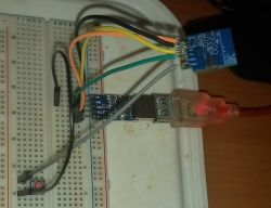
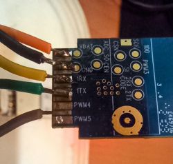
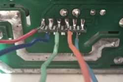
    I first tried flashing in-circuit. I was hoping that I don't have to desolder the WB2S since I have quite a few of these to do. Here are photos of the setup:
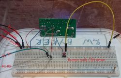
    Breadboard setup with connected PCB module, wires, and labeled UART lines and power supply.

    Close-up of a PCB with five colored wires soldered to the pins of a WB2S module.

    It powers on, and my reset button also works, but alas, it fails to flash. I have tried both power cycle and pressing the reset button many times.
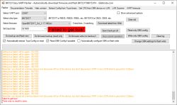
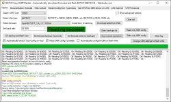
    Screenshot of BK7231 Easy UART Flasher software showing a Failed to get bus! error in red.

    I had my oscilloscope hooked up to the UART lines. Yellow is PC TX -> WB2S 1RX. Green is WB2s 1TX -> PC RX. It never replies. Something must be pulling that pin high.
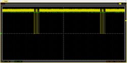
    Oscilloscope display with two traces, yellow and green, showing digital signal activity on a black grid background.

    Any bright ideas before I desolder it and try to flash out-of-circuit?
  • ADVERTISEMENT
  • #2 20691644
    p.kaczmarek2
    Moderator Smart Home
    Please attach photos to the our forum system if you can, otherwise we'll at risk that they will expire after some time. Anyway, I can see some potential problems here.

    Your wiring connection looks long, in noisy environment it's not recommended to connect that way, we had already users on the forum where making wires shorter helped.

    CEN RESET may not be reliable, I usually do power off/on cycle.

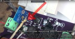
    If something is pulling UART high, you may have the same situation as we had on that video (GPIO had a capacitor connected, the useless capacitor, by the way, because we do debouncing in code):


    Close-up of a PCB with a relay module showing the process of removing an SMD capacitor from the RX pin.
    You can try the method from this video, even with hid_download_py, it should work.
    WARNING: the commands here are for CB2S (BK7231N), if you want commands for WB2S (BK7231T) see here:
    https://www.youtube.com/watch?v=Yb3zXtBdSnE
    WB3S is like WB2S, just different form factor.

    If it's still not working, we have also a video with desoldering method and a newer flash tool here:


    Please watch both videos and let us know if you have any questions. By the way, also remember to enable PowerSave 1 on your device, as it looks very cheap, and I know that some of Tuya power supplies just straight up require PowerSave 1 to work correctly without degrading capacitors quality.
    Helpful post? Buy me a coffee.
  • #3 20692690
    rudolfbyker
    Level 4  
    Thanks for the help!

    Unfortunately, I don't have a USB-UART with a shorter cable right now. I'll try to get one.

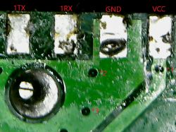
    I had a look at the circuit under a USB microscope. Assuming that it's only a 2-layer PCB, I can't see anything connected to TX or RX!

    Close-up of a two-layer PCB with markings TX, RX, GND, and VCC, and vias labeled *1, *2, and *3.

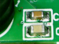
    Image of a PCB with two elements marked as vias, possibly bypass capacitors, labeled as *1 and *2.

    *1, *2 and *3 are vias to the capacitors on the other side, so they must be bypass capacitors.

    It looks like only VCC, GND, PWM0 and PWM5 are used. Is it possible?

    In any case, I have desoldered the WB2S and will try to flash it separately.
  • ADVERTISEMENT
  • #4 20692724
    p.kaczmarek2
    Moderator Smart Home
    No, I would rather say that you need at least 3 GPIOs here, because you need:
    - relay
    - pairing led
    - button
    So at least one more GPIO is most likely used here.

    Please do a 2MB flash backup before flashing OpenBeken, because we can extract GPIO roles easily from that 2MB flash. This will be helpful later, when we'll be configuring the device.
    Helpful post? Buy me a coffee.
  • #5 20692733
    rudolfbyker
    Level 4  

    That makes sense! There are a lot of components, but I can't see how they connect to the WB2S... Maybe there is a via inside one of the solder pads, and it's a more than two-layer PCB? *shrug*

    When you say "2MB flash backup", do you mean this button? Or is it something else?

    Button labeled Do firmware backup (read) only

    Luckily, I have 8 of these, so I can use another one if I mess things up.
  • #6 20692794
    p.kaczmarek2
    Moderator Smart Home
    Ok, so maybe try with a multimeter? Use continuity test to check whether is there a connection from one of GPIOs (from RX to TX) to a button or to a nearby capacitor?

    As we've said on that "smart switch flashing" video, the capacitors on RX and TX are not needed, you can remove them permanently.

    The "do firmware backup" option is good, although the option "do firmware backup first and then flash" is also good.
    Helpful post? Buy me a coffee.
  • #7 20693283
    rudolfbyker
    Level 4  
    p.kaczmarek2 wrote:
    Ok, so maybe try with a multimeter? Use continuity test to check whether is there a connection from one of GPIOs (from RX to TX) to a button or to a nearby capacitor?


    That is the first thing I tried! :) I tested every pad. I went over everything twice. Nothing has a connection to the TX or RX pins, that I could find. Maybe we will see something in the firmware backup.

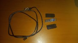
    I was using this USB-UART converter. https://www.netram.co.za/adapters/9611-pl2303...to-uart-rs232-com-cable-module-converter.html I opened it up and removed the long wires:

    A photo of a USB-UART converter with partially removed casing on a wooden surface next to a cable.

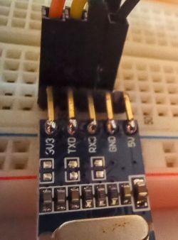
    The setup is much cleaner now:

    USB-UART adapter connected to a breadboard.
    Close-up of a circuit board with connected colored wires.
    Close-up of a USB-UART converter connected to a breadboard.

    I'm getting this error now, but I'll try again after a reboot:

    
    Backup name is set to connex_cc_p2000.
    Starting read!
    Now is: Monday, 14 August 2023 16:31:52.
    Flasher mode: BK7231T
    Going to open port: COM7.
    Serial port open exception: System.IO.IOException: A device which does not exist was specified.
    
       at System.IO.Ports.InternalResources.WinIOError(Int32 errorCode, String str)
       at System.IO.Ports.SerialStream..ctor(String portName, Int32 baudRate, Parity parity, Int32 dataBits, StopBits stopBits, Int32 readTimeout, Int32 writeTimeout, Handshake handshake, Boolean dtrEnable, Boolean rtsEnable, Boolean discardNull, Byte parityReplace)
       at System.IO.Ports.SerialPort.Open()
       at BK7231Flasher.BK7231Flasher.openPort() in W:\GIT\BK7231GUIFlashTool\BK7231Flasher\BK7231Flasher.cs:line 95
    Failed to open serial port!
    There was no result to save.
    
  • #8 20693290
    p.kaczmarek2
    Moderator Smart Home
    Is any serial port visible within the app?

    Maybe you've got something running in background and taking over the serial port? I remember that Cura slicer is doing that.
    Helpful post? Buy me a coffee.
  • #9 20693294
    rudolfbyker
    Level 4  

    Great success, after rebooting my machine :) I don't know what was using the COM port, but it's gone now.

    Screenshot of BK7231 Easy UART Flasher software with successful data reading.
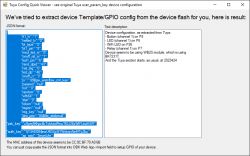
    Screenshot of Tuya device configuration with GPIO port information and JSON data.

    Text description:

    
    Device configuration, as extracted from Tuya: 
    - Button (channel 1) on P8
    - LED (channel 1) on P6
    - WiFi LED on P26
    - Relay (channel 1) on P7
    Device seems to be using WB2S module, which is using BK7231T.
    And the Tuya section starts, as usual, at 2023424


    JSON format:

    
    {
    	"rl1_lv":"1",
    	"netled_lv":"0",
    	"bt_type":"0",
    	"bt1_pin":"8",
    	"mxcl_led_m":"0",
    	"onoff_rst_m":"1",
    	"led1_pin":"6",
    	"rand_dpid":"43",
    	"net_trig":"0",
    	"led_dp":"40",
    	"onoff_n":"3",
    	"jv":"1)9Bgw_wsm{fsw_cnt_key",
    	"passwd":"null",
    	"md":"0",
    	"random":"0",
    	"wfb64":"1",
    	"stat":"0",
    	"token":"null",
    	"region":"null",
    	"reg_key":"null",
    	"dns_prio":"00$Bis_stridenull",
    	"psk_key":"u9yrej9Khjw4kTvkkedPmuTELOExWlFUxdHSR",
    	"auth_key":"7jY3AD084jnaU6DLbNTWoksnNeMTyZbu",
    	"ap_ssid":"SmartLife",
    	"ap_passwd":"null",
    	"country_code":"CN",
    	"bt_mac":"null",
    	"bt_hid":"null",
    	"prod_test":"false }.0.0",
    	"lock_dp":"41",
    	"nety_led":"0",
    	"netled_pin":"26",
    	"total_stat":"2",
    	"bt1_lv":"0",
    	"reset_t":"4",
    	"ch_flag1":"1",
    	"inch_dp":"44",
    	"module":"WB2S",
    	"ch_cddpid1":"9",
    	"clean_t":"5",
    	"init_conf":"38",
    	"led1_lv":"0",
    	"cyc_dpid":"42",
    	"ch_num":"1",
    	"reuse_led_m":"0",
    	"rl1_pin":"7",
    	"netn_led":"1",
    	"ch_dpid1":"1",
    	"crc":"56",
    	"}BAfsw_cnt_key0fsw_cnt_key":"2"
    }


    The 2MiB backup is attached. I never paired this device, so it does not contain anything sensitive, other than maybe the MAC address.
  • #10 20693325
    p.kaczmarek2
    Moderator Smart Home
    Thank you, now the final thing you need to submit is the template from our Web App, just also make sure to fill the image and forum topic links, if you can. That will allow us to add the device to this list:
    https://openbekeniot.github.io/webapp/devicesList.html
    We're going to reach 400 entries soon, so every device counts.

    Btw... your device has two separate LEDs, you are lucky. This can be configured in many ways, for example, one led can follow the relay state, or can be set to LED_n, so it's an inverted relay state.
    Helpful post? Buy me a coffee.
  • #11 20693348
    rudolfbyker
    Level 4  

    Exciting stuff :)

    Sorry, I'm not sure what you mean by Web App. I am trying to find and read all the relevant documentation, but it's a bit confusing and all over the place, so I have not seen anything about a web app yet...
  • #12 20693391
    p.kaczmarek2
    Moderator Smart Home
    Do you have any suggestions how to improve the docs?
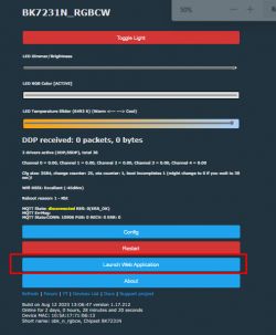
    User interface with options for the BK7231N_RGBCW device.
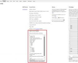
    Here is final OBK template (not the Tuya JSON):
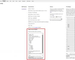
    Screenshot of OBK template documentation highlighting export option.
    Helpful post? Buy me a coffee.
  • ADVERTISEMENT
  • #13 20693879
    rudolfbyker
    Level 4  

    p.kaczmarek2 wrote:
    Do you have any suggestions on how to improve the docs?

    I will try to make constructive suggestions when I have improved my understanding of what is going on. Currently, I'm still too confused.

    I filled in my WiFi details in the flasher and flashed the chip successfully, but I don't see it connecting to my WiFi yet. I'm assuming that it does not need to be soldered back to do this because it has the antenna on board.

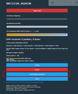
    Configuration interface for BK7231N_RGBCW device with LED control options.
    Where do I find this program? In all of the videos I have watched, the instructions jump from soldering/cleaning the PCB to this screen without saying how to get there.

    Screenshot of a device configuration interface showing network details and an export template option.
    Same question. Where do I find this program?
  • Helpful post
    #14 20693893
    p.kaczmarek2
    Moderator Smart Home
    You either connect to OBK AP and open page at 192.168.4.1 or if OBK is already configured, it connects to your WiFi and you just connect to it's IP from DHCP.

    It should automatically connect when configured, you only need to power off it and power on, even if you have module just powered by 3.3V. If it's not, then you either have wrong password or ssid, or you are experiencing some strange rare WiFi problem.

    I think it was reported 2 or 3 times already on this forum, and some guy also solved it with changing some WiFI setting on router or something. Maybe also clearing RF partition could help, but this can harm your signal quality so don't try it first.

    Maybe let's start by doing quick 5 power off/on cycles to boot into safe mode and check whether OBK Access Point shows up? Can you connect to OBK access point then?
    Helpful post? Buy me a coffee.
  • #15 20694253
    MnM1
    Level 10  

    "Maybe let's start by doing quick 5 power off/on cycles to boot into safe mode."

    @p.kaczmarek2 - when you say quick, what do you actually mean? How many seconds in between each ON and OFF?
  • #16 20694300
    p.kaczmarek2
    Moderator Smart Home
    It depends. There are two factors at play:
    - the off cycle must be long enough for capacitors to discharge, so the BK really turns off. That cycle may need to be longer if you have PowerSave enabled. Basically, BK must turn off, because you know, if you have a very low load on power supply then turning of power for 0.25s may not be long enough for capacitors to discharge...
    - the on cycle must be shorter than "boot ok mark" setting from OBK options:
    Screenshot of a setting for uptime seconds required to mark boot as ok.

    I would say that 2 seconds is a safe value in both cases.

    The logic behind scenes is very simple. On boot start, the boot counter is increased. After 5 (CONFIGURABLE - see above) seconds, if device still runs, the correct boot counter is set to the current boot counter.
    Futhermore, also on boot start, the correct boot counter is compared with current boot counter. If the difference is 5 or higher, then safe mode kicks in and opens access point.
    Helpful post? Buy me a coffee.
  • ADVERTISEMENT
  • #17 20694327
    MnM1
    Level 10  
    I have a downlight that was working fine before. I was testing a smart switch and somehow that downlight now seems to be in permanent OFF state.
    I have tried the above steps but I can get the device to wake up let alone to go into AP mode. Are the any other methods to rescue the device?

    Plugged the downlight into a smart power plug to see if there is any W or A draw (thinking that maybe it comes back without wifi and without rescue AP mode) but there is always 0W and 0A showing.
  • #18 20694350
    p.kaczmarek2
    Moderator Smart Home
    Please open separate topic and we'll investigate it, but long story short, your problem description could mean that something else than WiFi module is at fault. Maybe broken power supply? The WiFi module should be taking some small current, even if it's not connected.
    Helpful post? Buy me a coffee.
  • #19 20695003
    rudolfbyker
    Level 4  

    Sorry for the slow replies. I can only spend around 30 minutes per day on this. My journey continues:

    I had lots of trouble with the COM port on Windows. It would stop working after some time, then I had to reboot to get it working again. So I followed the instructions here and here and added myself to the `dialout` user (on Ubuntu / LinuxMint). It seems to work more consistently with Linux than Windows.

    I removed my WiFi credentials using the flasher, and restarted the WB2S. It created the hotspot, and I could connect to it! I poked around there a bit, and then decided to enter my WiFi credentials there. It then restarted, and it unfortunately did not connect to my WiFi.

    I pressed the CEN button 5 times, 2 seconds apart, and then the OBK access point showed up, and I could connect to it again. It told me we are not in "Safe Mode" as expected. I tried to open the web app in safe mode, but it said "Not Found". So I converted it back to an open access point, and then I got the web app like in your second screenshot.

    I'm not sure where to go from here. Is there some kind of persistent log that can show me what went wrong when it tried to connect to WiFi?
  • Helpful post
    #20 20695186
    p.kaczmarek2
    Moderator Smart Home
    So basically your issue is that the device does not connect to your WiFi?

    Well, we had a user with exactly the same problem. You can try to searching for that, it was somewhere in this IoT section.

    This is a very rare problem, and I apologize for the inconvenience. We'll try to figure it out together.

    Steps to take:
    - triple check the MAC address displayed on your WWW panel, if you have accidentally cleared whole flash you might got 00 00 00 MAC, and if you did that already in the past, you might have gotten MAC duplication on your LAN
    - try the same steps on another BK7231 device and tell me if it's working
    - try to pair your device with another router or a mobile phone hot spot, just for the testing purposes
    - connect to TX2 pin and get the debug UART log from Beken


    rudolfbyker wrote:
    I tried to open the web app in safe mode, but it said "Not Found".

    There should be a button "do unsafe start" or something like that, that enables Web App in safe mode, but.... but Web App fetches from Github, so you need to have internet connection for that.
    Helpful post? Buy me a coffee.
  • #21 20695791
    rudolfbyker
    Level 4  

    p.kaczmarek2 wrote:
    Triple check the MAC address displayed on your WWW panel


    Build on Aug 15 2023 15:26:48 version 1.17.219
    Online for 5 minutes and 45 seconds
    Device MAC: CC:8C:BF:70:A0:6B
    Short name: sk1, Chipset BK7231T


    p.kaczmarek2 wrote:
    Connect to TX2 pin and get the debug UART log from Beken


    I did this with the chip configured to be an access point uart_acces..._point.txt Download (6.77 kB) AND with the chip configured to be a client uart_cli..t.txt Download (5.24 kB) . The latter periodically says "WIFI_STA_DISCONNECTED".

    The route is a Mikrotik hAP ac lite. It creates two separate hotspots for 2.4GHz and 5GHz. I just realized that I was using the SSID name as configured on the Mikrotik, but it appends " 2.4GHz" to the SSID name! After fixing the SSID, it connects to my WiFi without issues.

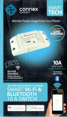
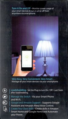
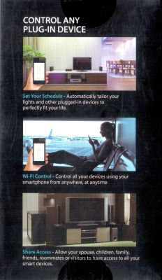
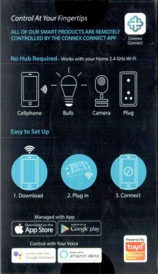
    Here are some images of the packaging:

    Packaging of Connex Connect Smart Wi-Fi and Bluetooth Switch.
    Smart WiFi switch packaging with smartphone app and lamp.
    Packaging showing graphics of remote control of devices via Wi-Fi.
    Connex Connect product packaging for remote control of smart devices.

    Here is the template. I don't know what to do with "board" and "keywords" and "bDetailed". I also don't know where to link to the manufacturer's page, which is https://connexconnect.com/product/smart-wifi-switch-10a/ For the "wiki" I am sure we can write a better topic than this one, but maybe this one will suffice for now:

    
    {
      "vendor": "Connex Connect",
      "bDetailed": "0",
      "name": "Smart WiFi Switch 10A",
      "model": "CC-P2000",
      "chip": "BK7231T",
      "board": "TODO",
      "flags": "0",
      "keywords": [
        "TODO",
        "TODO",
        "TODO"
      ],
      "pins": {
        "6": "LED;1",
        "7": "Rel;1",
        "8": "Btn;1",
        "26": "WifiLED_n;0"
      },
      "command": "backlog PowerSave 1;",
      "image": "https://obrazki.elektroda.pl/7322999100_1692195471.jpg",
      "wiki": "https://www.elektroda.com/rtvforum/topic3995489.html"
    }
    

  • Helpful post
    #22 20695811
    p.kaczmarek2
    Moderator Smart Home
    Well, so it works now? Good job! You really got me worried that we have some strange WiFi connect issue. Now, when I think about it, I have never experienced this issue myself, even though I flashed thousands of devices... hmm.

    Ok, the board field should say WB2S, keywords can be names of ICs on the PCB or SKU code, or FCC ID, but those are not important. They just help other people to search devices more effectively. For product link, you need a "product" field (just insert it, don't forget the comma), and bDetailed is used to mark detailed articles like:
    https://www.elektroda.com/rtvforum/topic3887748.html

    Feel free to ask any further questions. You can also post any other teardowns on our forum, even if device is non-Beken (ESP8266 is welcomed here as well).
    Helpful post? Buy me a coffee.
  • #23 20695831
    rudolfbyker
    Level 4  

    Yes, it's working. Thanks for all the help!! But I still have to re-solder it and learn how to connect it to Home Assistant. I'm assuming we use the MQTT integration?

    Updated:

    
    {
      "vendor": "Connex Connect",
      "bDetailed": "0",
      "name": "Smart WiFi Switch 10A",
      "model": "CC-P2000",
      "chip": "BK7231T",
      "board": "WB2S",
      "product": "https://connexconnect.com/product/smart-wifi-switch-10a/",
      "flags": "0",
      "keywords": [
        "WIFI401-N-V1.2",
        "OB2222MCP",
        "AMS1117",
        "YX202-S-105D"
      ],
      "pins": {
        "6": "LED;1",
        "7": "Rel;1",
        "8": "Btn;1",
        "26": "WifiLED_n;0"
      },
      "command": "backlog PowerSave 1;",
      "image": "https://obrazki.elektroda.pl/7322999100_1692195471.jpg",
      "wiki": "https://www.elektroda.com/rtvforum/topic3995489.html"
    }
    

  • #24 20695852
    p.kaczmarek2
    Moderator Smart Home
    We have some detailed guides on our Youtube channel:
    https://www.youtube.com/@elektrodacom
    For HA, you can use:


    Helpful post? Buy me a coffee.
  • #25 20696093
    rudolfbyker
    Level 4  

    Thanks again, I got it working with Home Assistant.

    One more question: Is the following correct?

    These are BK7231T pin numbers, not WB2S pin numbers:
    
    "pins": {
      "6": "LED;1",
      "7": "Rel;1",
      "8": "Btn;1",
      "26": "WifiLED_n;0"
    }


    Looking at https://developer.tuya.com/en/docs/iot/wb2s-module-datasheet?id=K9ghecl7kc479 to get the mapping of WB2S pins to BK7231T pins,
    - Pin 6 of the BK7231T is PWM0 on the WB2S, which is connected to the relay status LED.
    - Pin 7 of the BK7231T is PWM1 on the WB2S, which is connected to the relay.
    - Pin 8 of the BK7231T is PWM2 on the WB2S, which is connected to the button.
    - Pin 26 of the BK7231T is PWM5 on the WB2S, which is connected to the WiFi LED.

    So nothing is connected to 1TX or 1RX as I suspected at the start, so in-circuit flashing should be possible?

    Also, I should be able to use pin PWM4 to read the state of a toggle switch (not a momentary switch)?
  • #26 20696150
    p.kaczmarek2
    Moderator Smart Home
    If it's the config you've extracted from Tuya JSON, then it must be correct. I don't know why flashing in circuit didn't work. Maybe the power on/off cycle was not precise enough due to the capacitors on the board. Resetting via CEN also works, but timing is crucial.

    Any unused BK7231 GPIO can be configured in any way you like. You can add extra buttons, extra LEDs, Relays and even sensors like DHT11, etc
    Helpful post? Buy me a coffee.
  • #27 20696398
    rudolfbyker
    Level 4  
    Nice. I managed to configure an extra pin as a digital input, and now I don't have to replace the toggle switches in my house. It follows the switch when it changes, but it can also be changed from Home Assistant (in which case the switch is in the "wrong" position until someone comes along and interacts with it again). Perfect.

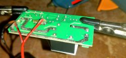
    Close-up of a circuit board with soldered wires and a mounting clamp.

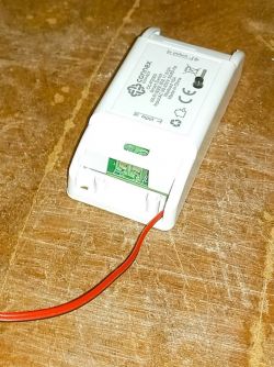
    A white Connex Connect Smart WiFi Switch 10A module with a red wire attached, resting on a wooden surface.

    I also saw that the relay's LED needs to be inverted, so the template becomes:

    {
      "vendor": "Connex Connect",
      "bDetailed": "0",
      "name": "Smart WiFi Switch 10A",
      "model": "CC-P2000",
      "chip": "BK7231T",
      "board": "WB2S",
      "product": "https://connexconnect.com/product/smart-wifi-switch-10a/",
      "flags": "0",
      "keywords": [
        "WIFI401-N-V1.2",
        "OB2222MCP",
        "AMS1117",
        "YX202-S-105D"
      ],
      "pins": {
        "6": "LED_n;1",
        "7": "Rel;1",
        "8": "Btn;1",
        "26": "WifiLED_n;0"
      },
      "command": "backlog PowerSave 1;",
      "image": "https://obrazki.elektroda.pl/7322999100_1692195471.jpg",
      "wiki": "https://www.elektroda.com/rtvforum/topic3995489.html"
    }
  • #28 20696454
    p.kaczmarek2
    Moderator Smart Home
    Just please be aware that this particular model of smart device runs on non-isolated power supply, so there is a risk of getting live potential on the wire you route out. It may be a serious safety issue, depending on how and where you connect that.


    Hmm but are you sure that you want digital input? From your description, it sounds like you want a "TglChannelOnToggle" pin type.
    Helpful post? Buy me a coffee.
  • #29 20696508
    rudolfbyker
    Level 4  

    p.kaczmarek2 wrote:
    Just please be aware that this particular model of smart device runs on non-isolated power supply


    I saw that. Indeed, not ideal. Just to make it clear for people reading this who don't see why this is dangerous: It means that the GND pin of the WB2S chip is connected directly to the Neutral wire. So if you were to accidentally swap Neutral and Live, one of the new wires that I brought out in the photo above would be connected to Live (which is around 220V – 240V in South Africa). So make sure you get the polarity right, and double-check everything with a multimeter.

    p.kaczmarek2 wrote:
    Hmm but are you sure that you want digital input?


    Yes. I tested it, and it's the behavior I want. I.e. I want a specific switch position to have a specific meaning, rather than just toggling it and seeing what the light does.

    Lastly, do we have enough info in this thread for me to make a PR for https://github.com/OpenBekenIOT/webapp/blob/gh-pages/devices.json or do you prefer that I make a tidy write-up about this module in a separate thread? (It might take a while before I find the time.)
  • #30 20696667
    p.kaczmarek2
    Moderator Smart Home
    The latest version of JSON is very good, you can make a pull request right now. There is no need to describe that device again, but you are welcome to post information about another device model. We're trying to get past the 400 devices mark soon. I have myself over 10 more devices in queue to present, but as a developer I have to pool time between different tasks so the teardowns will be posted within next month or two:
    Screenshot of a folder with file names of devices and dates.
    Our list here: https://openbekeniot.github.io/webapp/devicesList.html is steadily growing and we are going to make it even bigger soon.
    Helpful post? Buy me a coffee.

Topic summary

The discussion revolves around the flashing process of the Connex Connect CC-P2000 10A Smart WiFi Switch, which contains a WB2S module. The user initially faced challenges with wiring, UART connections, and firmware flashing. After troubleshooting, including using a USB-UART converter and examining the PCB, the user successfully extracted the device configuration and flashed the firmware using the hid_download_py tool on Linux. The device was eventually connected to WiFi after correcting the SSID issue. The user also configured additional features, such as a digital input for a toggle switch, and shared insights on the device's pin mapping and safety considerations regarding its non-isolated power supply.
Summary generated by the language model.
ADVERTISEMENT