logo elektroda
logo elektroda
X
logo elektroda

[BK7231N] [CBU] Tuya Light + PIR Motion Sensor (FH_PIR_400A)

auntlydia 6042 50
ADVERTISEMENT
  • Hello,

    I would like to present teardown and my user experience of this module:

    Tuya Light + PIR Motion Sensor (FH_PIR_400A) --> AliExpress-Link

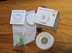
    First, some photos of package and content:
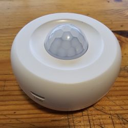
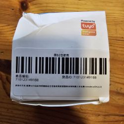
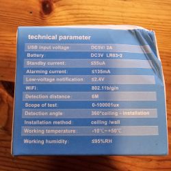
    White, round PIR motion sensor with USB port, placed on a wooden surface. Tuya product box with a barcode and Tuya logo. Technical parameters from Tuya motion sensor packaging Packaging and contents of the Tuya PIR motion sensor kit

    Pry to open carefully under reset button, then insert some flat tool to separate the two halves of housing by stretching the gap:
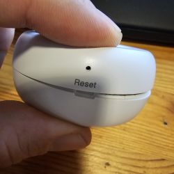
    Close-up of a hand holding a small white device with a reset button on the casing.

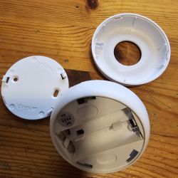
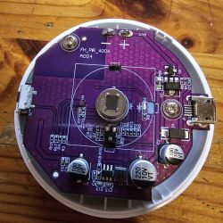
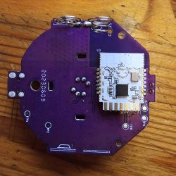
    Now have a look at parts and module:
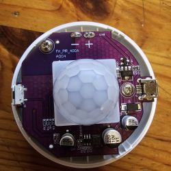
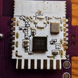
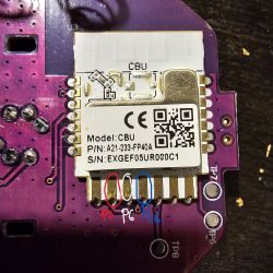
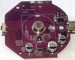
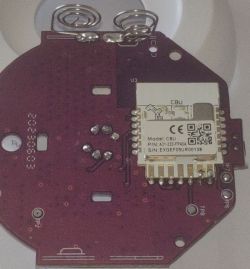
    Disassembled housing of a motion and light sensor. PIR sensor module in an open casing, showing electronic components. Tuya module PCB with microphone and MicroUSB port Electronic module on a purple PCB with a CBU component. Close-up of a circuit board with a CBU module and BK7231 chip.

    We have a very similar module in this post: https://www.elektroda.com/rtvforum/topic3982613.html

    But here we have a CBU module and an additional light sensor which can measure light intensity by Lux at a range between 0 ~ 6500, give or take:
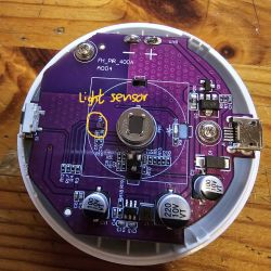
    Interior of the module with a labeled light sensor on the circuit board.

    A few things about device and flashing:

    - it is not a TuyaMCU device
    - there is no need to cut connections or desolder CBU module
    - flashing works flawlessly with bk7231flasher Windows tool
    - the device can be powered with 2xAAA batteries, which makes sense with deep sleep driver (Door Sensor function)
    - it can also be powered with 5V via MicroUSB
    - the reaction time until Wifi is connected and status reported with OpenBK deep sleep is about ~5 seconds
    - without deep sleep the Wifi connection is kept stable and it reacts instantly on motion
    - After detecting motion, it changes to "Clear" within ~5 seconds when no further motion is detected
    --> edit: I have bought several of those devices, and actually only the first one I bought has this fast clearing of motion interval, all the others take 30 seconds to change the status to "Clear" when no further motion is detected.

    I was able to assign following functions to pins:

    P8: motion detector --> dInput(_n) / DoorSnsrWSleep (whichever suits better)
    P16: LED --> LED(_n) / WifiLED
    P23: Battery --> BAT_ADC (choose different channel here)
    P24: Reset Button --> btn

    bkflasher was unable to extract information from original firmware read.

    Here is the file: Tuya_Motio...Sensor.bin Download (2 MB)Points: 1 for user

    Home Assistant discovery works on the spot:
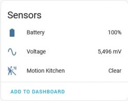
    Sensor widget displaying battery status, voltage, and motion sensor status.

    Unfortunately, I was unable to get the light sensor working. I tried GPIO doctor with all the pins dInput with and without pullup, no success. Any contribution to make the light sensor work would be appreciated.

    Cheers!

    Cool? Ranking DIY
    About Author
    auntlydia
    Level 10  
    Offline 
    auntlydia wrote 62 posts with rating 11, helped 1 times. Been with us since 2023 year.
  • ADVERTISEMENT
  • #2 20722881
    p.kaczmarek2
    Moderator Smart Home
    So U4 is a light sensor? Are you able to check with multimeter to which GPIO it connects to? It looks like it might have two data lines, is it possible it's something like a I2C sensor?
    Helpful post? Buy me a coffee.
  • #3 20723965
    auntlydia
    Level 10  

    Hi, thanks for your reply!

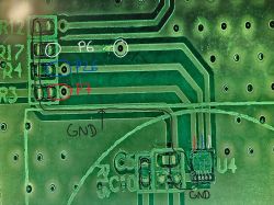
    I was able to trace back the connections, there are 3 connections directly to CBU pins! That is very interesting!!

    Let's have a look:

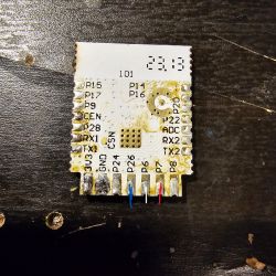
    Image of a PCB with marked pins P6, P7, P26, and GND. Electronic module with marked pins P6, P7, and P26. Close-up of a PCB with pins labeled with various symbols and colored wires.

    The connections arrive at P6, P7, and P26 of CBU, which are all PWM pins. The other side of the light sensor is connected to GND.

    I am not sure about I2C... until today I had no knowledge about it but read a bit and understand that there are two data lines (SDA and SCL), between the host (main device) and slave (sensor). We seem to have three lines here, all of which are data lines.

    Can you make something of this information? Thank you.
  • #4 20724029
    p.kaczmarek2
    Moderator Smart Home
    Maybe we can search for I2C light sensors online and see if there are any similar to the one you have on the board.
    Helpful post? Buy me a coffee.
  • #5 20724523
    dgel27
    Level 7  
    Hi,
    i have ordered this PiR Sensor:

    [BK7231N] [CBU] Tuya Light + PIR Motion Sensor (FH_PIR_400A)

    Inside it contain LED, BUTTON, PiR sensor, Battery monitor and Light sensor (U4 on the board):
    Electronic module with PiR sensor and various components on a purple PCB CBU module on red printed circuit board with visible test points.

    The device build on TUYA CBU module and contain testpoints TP6 and TP7 (Tx and Rx) from the module. I cannot re-flash it with tuyacloud, only with BK7321 Flash tool. Also, non Flash tool, not tuya cloudcutter cannot extract tyua template (the Tyua firmware attached)

    From my investigation i found connection for this device:
    P8 - PiR sensor
    P16 - LED /WiFi LED
    P24 - Button
    P23 - Batt ADC (coefficient 1.97 work fine for me)
    P22 - Batt Relay

    Light sensor (U4 on the board):
    P6 - I2C clock
    P7 - I2C data
    P26 - programmable interrupt from light sensor, when the light strong(over the range), the signal fall down

    I dont know what is a light sensor, but i attach 2 PulseView files:
    - one is Tuya FW sensor capture
    - OBK power on sensor capture

    I tried to execute scanI2C command, i have see OK result, but i cannot see anything on the bus (the signals is not changes, and was always high). Maybe i dont execute the command right way, but threre no info about this command.

    I will glad if this driver will be implement in OBK firmware.

    Thanks
  • #6 20724577
    ferbulous
    Level 18  
    Hi, on the stock firmware
    Do you only get light sensor updates when there's motion detected?
  • ADVERTISEMENT
  • #7 20724587
    auntlydia
    Level 10  
    Hi, I had a look at mouser to see if I can find any. It seems not a very easy task, there are many different kinds which look similar, and it is hard do tell what is the difference as a non-professional.

    Here is mouser search result for "ambient light sensor": https://www.mouser.com/c/optoelectronics/optical-detectors-sensors/ambient-light-sensors/

    Those are few ones which I found most similar, but I think they are not the same:
    https://www.mouser.de/datasheet/2/239/Lite-On_LTR-303ALS-01_DS_ver%201.1-1175269.pdf
    https://www.mouser.de/datasheet/2/588/TSL2521_Short_Datasheet_DS001010_1_00-2584593.pdf
    https://docs.broadcom.com/doc/APDS-9251-001-DS

    So, how is the process with unknown I²C components? Do we need to do reverse engineering and read/encrypt data that is sent through I²C bus? I suppose special equipment and some electric knowledge is required here? Or if we are lucky we can find the required data of components in docs and data sheets?
  • #8 20724589
    dgel27
    Level 7  

    Hi,
    On the stock firmware, the module stays in deep sleep mode.
    The motion or interrupt from a huge light source (flashlight from a mobile), and it updates 3 things:
    - motion
    - light (lumens)
    - battery percentage

    Thanks!
  • #9 20724626
    auntlydia
    Level 10  

    Oh, awesome! As I see, you have done the job of analyzing this light sensor? Yes, combining this topic would be the best. So, with your data, maybe the developers can try to make it work in OpenBK!
  • #10 20724631
    dgel27
    Level 7  

    Per footprint, it seems LTR-303-ALS-01.
    Others don't fit the footprint/pinout.
  • #11 20724710
    p.kaczmarek2
    Moderator Smart Home
    It seems that I2C address is 38:
    Screenshot from a logic analyzer showing I2C signals with addressing and data writing.
    I've read on the other thread that it may be LTR303, but it doesn't seem to match:
    https://github.com/automote/LTR303/blob/master/LTR303.h
    Also the addresses they write to seem different, but maybe I am wrong?

    Do you still have logic analyzer hooked up? I could write some basic code with LTR303_PART_ID request so we can tell whether it's LTR303
    Helpful post? Buy me a coffee.
  • #12 20724750
    dgel27
    Level 7  

    Yes, the slave address doesn't match. But pinout exactly fits. I also looked for all LiteOn sensors and cannot find 0x38.
    Maybe something is wrong with my analyzer, it's a simple $5 board. I have a Keysight at work, but it will be next week.
    Is it possible to scan addresses in OBK?
  • #13 20725244
    p.kaczmarek2
    Moderator Smart Home
    The scan function you've found was for the hardware I2C bus. Apparently the hardware bus is not used often and our drivers are implemented now as bit-bang in software. Still, if you think that could helpful, hmm... I can think about something and add some kind of generic I2C scanner for software I2C.
    Helpful post? Buy me a coffee.
  • ADVERTISEMENT
  • #14 20725830
    dgel27
    Level 7  

    I think it will be great.
    Take pins marked as SoftSDA and SoftSCL (or some other type, just for scanning) and scan full addresses.

    It will be great for someone (like me) who wants to add some sensors to current devices.
    I want to use this device and add an I2C weather sensor to the I2C bus and an IR Tx LED to an unused pin. In one nice package, I will have all necessary sensors for the room.

    And many thanks to you for excellent work!
    I'm ready to help with the project to the best of my abilities.
  • #15 20725894
    auntlydia
    Level 10  
    Wow! This is a really cool idea, to add weather sensors and extend the function of this sensor board. Could you share your project here in this thread and explain how you do it? I would be interested to follow the progress...


    @p.kaczmarek2 , thanks for combining our topics! :)

    Added after 3 [hours] 5 [minutes]:

    I was trying to find the sensor again with google search, found some similar ones but that one seems hard do get. I will try to ask a Chinese friend if they can find it in Chinese internet.
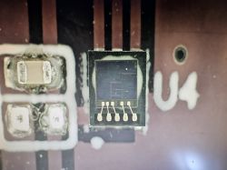
    I want to share another photo I took under the microsope. We have 5 internal pins inside the sensor, and it looks like the SMD package has 6 pins, 3 on each side, similar to the LITEON one.. in my photo it looks slightly rectangular, but actually it is square shaped! (display problem)
    Close-up of a sensor on a PCB under a microscope.

    maybe wil fill find it still!
  • ADVERTISEMENT
  • #16 20739000
    p.kaczmarek2
    Moderator Smart Home
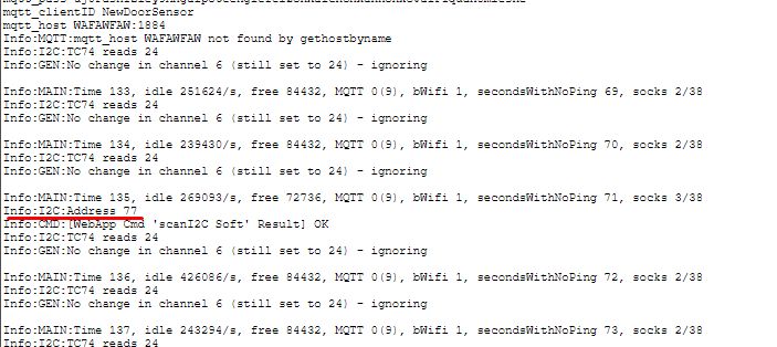
    I2C scanner works:
    Screenshot of a system log showing information about I2C scanning with device identification.
    Usage:
    1. set SoftSDA and SoftSCL pins
    2. use:
    
    startDriver I2C
    scanI2C Soft
    
    Helpful post? Buy me a coffee.
  • #17 20739223
    auntlydia
    Level 10  
    Hi, thanks!

    I tried with setting P6 to SoftSCL and P7 to SoftSDA, as @dgel27 suggested thad I2C communication is handled through those. Then I set the driver via autoexec.bat and restarted. Now I use a strong flashlight to trigger the sensor, but I don't get any result in log about I2C. Am I using the correct approach here?

    As P26 seems to be the pin where the lux value arrives, which function should we assign to that pin?

    Thanks for help!
  • #18 20739260
    p.kaczmarek2
    Moderator Smart Home
    No, it doesn't work that way. It's just I2C scanner, it will print addresses of I2C devices detected on the bus. It's not a complete device driver.

    Execute:
    
    scanI2C Soft
    

    from the Web App console and it should print the address of the sensor. Make sure to start I2C driver first.
    Helpful post? Buy me a coffee.
  • #19 20739275
    auntlydia
    Level 10  
    OK, I understand. I get

    Info:CMD:[WebApp Cmd 'scanI2C Soft' Result] OK

    but I don't get I2C result! Do I need to specify different channels for the data/clock buses? I tried both with channel 0 and other unused channel, but no difference.
  • #20 20739310
    p.kaczmarek2
    Moderator Smart Home
    Channels will not affect behaviour of the scan.

    Maybe you've swapped SDA with SCL?

    It should detect a single device address, hm...

    Or maybe you haven't updated OBK?
    Helpful post? Buy me a coffee.
  • #21 20739322
    auntlydia
    Level 10  
    I updated to newest OpenBK (246) just before I tried it. The driver is activated and loaded. I have tried SDA and SCL on both P6 and P7, and also P26. There is no message on I2C in logs.
  • #22 20739354
    p.kaczmarek2
    Moderator Smart Home
    You can't have two SDAs, nor also two SCLs.

    You must have only a single SDA and single SCL.

    Please fix and try again.
    Helpful post? Buy me a coffee.
  • #23 20739406
    auntlydia
    Level 10  
    I'm sorry, I was not clear... I tried both:

    P6 - SDA
    P7 - SCL

    and

    P6 - SCL
    P7 - SDA

    and to be sure, I have tried possible combinations of SDA and SCL between P26 and P6 / P26 and P7, to be sure. But I haven't put SDA or SCL double at the same time.

    Is a restart required if pin settings are changed?

    I also double checked to enable "I2C" in log level.
  • #24 20739484
    p.kaczmarek2
    Moderator Smart Home
    I just realized something...

    Can you update OBK now and try again?

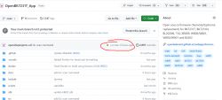
    I am sure you had incomplete version of the scanner:
    Screenshot of a GitHub repository page showing the OpenBK7231T_App branch.
    I committed it 6 hours ago but the push didn't go trough.
    Helpful post? Buy me a coffee.
  • #25 20739506
    auntlydia
    Level 10  
    nice!

    this is what I get now:

    Info:I2C:Address 0x38 (dec 56)
    Info:CMD:[WebApp Cmd 'scanI2C Soft' Result] OK

    is that helping in order to make the sensor working?
  • #26 20739889
    dgel27
    Level 7  
    I'm also get 0x38.

    I have tried find device by datasheets with this address, and cannot.
    We need wait, or do some reverse engineering with logic analyzer, to find some commands, we can operate.

    @p.kaczmarek2 : I have add another I2C device on the bus (BMP280), and i cannot get results. Is scan support only one device?
    In electronics are no miracles, just bad contacts :)

    I can see 2 devices on the bus:

    Info:I2C:Address 0x38 (dec 56)
    Info:I2C:Address 0x76 (dec 118)
    Info:CMD:[WebApp Cmd 'scanI2C Soft' Result] OK

    Thanks,
  • #27 20739934
    p.kaczmarek2
    Moderator Smart Home
    This tells us it that it's really an I2C device.

    The next question is - which I2C device is it?

    Which I2C sensor looks like it and has 0x38 address?

    Added after 7 [minutes]:

    Maybe I should implement basic read for LTR303 and we will see how it goes?

    Added after 5 [minutes]:

    This could be useful:
    https://i2cdevices.org/addresses/0x38
    Helpful post? Buy me a coffee.
  • #28 20740507
    dgel27
    Level 7  
    It possibly to try, but registers addresses not fit.
    More closer registers adresses in LTR-390, LTR-381RGB, LTR-308, LTR-216, but also not fit that i see in logic analyzer.

    VISHAY have different pinout and different command sysytem - it uses 2 different addresses for read and write (0x38 and 0x39)

    But anyway, i think we have progress, if not in this device, but in full firmware.
    If we can detect device, it possible add many different drivers, and automatically add detected devices to the bus.
    This concept brings OBK to all development possibilities, not just devices present on the market currently.

    OK, we cannot find currently what is device with 0x38 address, ok, it possible order breakout board with known sensor, solder 4 wires... and WOW... we have additional light sensor, that works, and non-works wait for future use....

    Thanks!
  • #29 20741207
    auntlydia
    Level 10  
    @dgel27 great idea!
    would you mind do share your steps on how to add known devices to I2C bus and configure them to add their function of the module? maybe a little guide with commented photos would help some other people like myself.

    I have a spare CBU module from a broken device, which still works and could be used for some experimental project like this! I also have a spare motion sensor with 3 pins and could try to connect it, or some buttons or LEDs, or little siren. But I don't have enough knowledge yet which pin to connect where and then to configure it.

    I have flashed more than 20 devices now with OpenBK, it is super cool and makes me addicted somehow 😅I want to get to that point where I can erase all different smarthome apps from my phone and run everything independently and locally with Home Assistant or simple web interface.
  • #30 20741233
    p.kaczmarek2
    Moderator Smart Home
    How many steps are needed to get the measurement results with that device? Maybe we just could rewrite the steps observed into the logic analyzer into the code... of course assuming we know how we get the data and the data is in some simple format with not much postprocessing needed
    Helpful post? Buy me a coffee.

Topic summary

The discussion revolves around the teardown and user experience of the Tuya Light + PIR Motion Sensor (FH_PIR_400A). Participants analyze the internal components, particularly focusing on the light sensor (U4) and its connections to the CBU module. They explore the possibility of the light sensor being an I2C device, with discussions on pin configurations and data lines. Various users share their findings on the sensor's connections, including PWM pins and I2C data lines, and express interest in developing a driver for the sensor to enable its functionality with OpenBK firmware. The conversation also touches on the challenges of identifying the specific I2C device and the need for reverse engineering to understand its communication protocol. Additionally, there are suggestions for alternative Zigbee devices that offer similar functionalities without the need for complex setups.
Summary generated by the language model.
ADVERTISEMENT