
logo elektroda
logo elektroda
X
logo elektroda

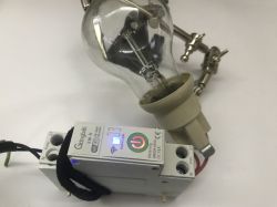
[BK7231N] [CBU] Tuya Light + PIR Motion Sensor (FH_PIR_400A)

auntlydia 8157 50

TL;DR LABEL_AI_GENERATED

  • Teardown and flashing notes for the Tuya Light + PIR Motion Sensor FH_PIR_400A with a BK7231N CBU module and an extra ambient light sensor.
  • It is not a TuyaMCU device, so it flashes directly with bk7231flasher without cutting traces or desoldering the CBU module.
  • The light sensor is supposed to measure about 0~6500 lux, and the board can run from 2xAAA batteries or 5V via MicroUSB.
  • OpenBK deep sleep brings the device online and reports status in about ~5 seconds, while always-on Wi‑Fi gives instant motion response.
  • Home Assistant discovery works immediately, but the ambient light sensor could not be made to work with GPIO Doctor on any tested pin.
AI summary based on the discussion. May contain errors.
ADVERTISEMENT
Listen:
  • Everlight EAALSDIC2020A2 sensor identified at 0x38

    #31 20741282
    auntlydia
    Level 10  
    Posts: 70
    Help: 2
    Rate: 15
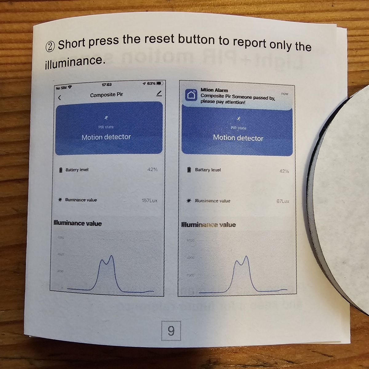
    Not sure if this is helpful but I just found this in the device's instructions manual:
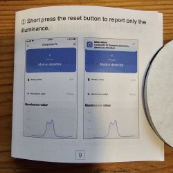
    Page from a manual showing a light level graph on a device.

    So, apparently only (?) lux value is reported upon short button press with original Tuya firmware. Would it be possible to sniff some useful data during this process?

    It is also said that a long button press reports both battery level and illuminance.

    It actually CAN be helpful to read those manuals every now and then.. 😅 I usually leave them in the package because most of the time they seem useless.

    Furthermore, the manual states that the lux sensor range is 0-10000. If this represents the actual sensor's range, it could help narrowing down the search for the SMD component.

    I wonder if the button press and the sensors are actually connected physically, independent from the firmware, or if the firmware does the job of connecting them and initialise the sensor read and send of the value report... if I have time, I will use GPIO doctor to see if there is any reaction on P26, P7 or P6 if I press the button.

    Added after 1 [hours] 39 [minutes]:

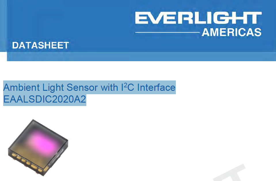
    ....and.. one more thing. a while ago I had found some datasheet during my research for this light sensor (I think it was actually through google picture results).. the sensor looks similar from the product picture on the PDF.. the name is "Ambient Light Sensor with I2C Interface EAALSDIC2020A2" (Everlight Americas)
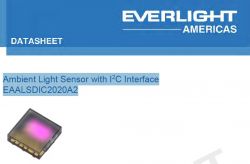
    Cover of the datasheet for the EAALSDIC2020A2 ambient light sensor with I²C interface from Everlight Americas.

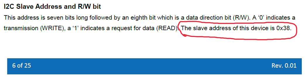
    Now with scrolling through the sheet, I found that the Slave Address is 0x38!!!
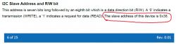
    Snippet of technical documentation with the Slave address 0x38 highlighted.

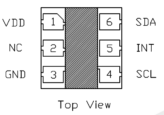
    And the pinout seems to match as well, at least SDA and SCL have the same position as we found here in our analysis, and the middle pin (--> P26) is labelled as INT ("Interrupt pin")
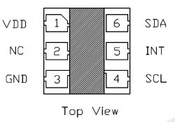
    Top view of an electronic component pin layout with labels VDD, NC, GND, SCL, INT, SDA.

    I'll attach the PDF here for those of you who understand more about electronics. Maybe we are very close to a solution now!
    EAALSDIC2..A2.pdf (828.75 kB)You must be logged in to download this attachment.
  • ADVERTISEMENT
  • I2C bus support and device-driver strategy for OBK

    #32 20741344
    dgel27
    Level 8  
    Posts: 19
    >>20741207
    Hi @auntlydia, this is not my idea. Evrehyng depend on @p.kaczmarek2 and firmware. from HW point, I2C bus is very simple: all devices attached to bus with 2 lines in parralell: data and clock (plus 2 lines power). Each device must have 7bit uniquie address (manufcturer give it, but may a bit configure with hw pins). Access to device - via this address. So, MCU theoretically serve till 128 devices on 2 GPIO pins.
    Exept HW, we need SW, that:
    1. Detect device on the bus (scan all 128 addresses, and see on which we have answer) - now it works in OBK!
    2. Can work with that devices (need configure device, read data from it, reset, if need - all via I2C commands, and every device different). So we need code per device. The known devices have this code, just need implement it in OBK. Each cote take space on the MCU flash, so need to think about build system, to user will compile code with modules he need.
    3. FW have input/output data to MQTT for automation
    These implemented in Tasmota (ESP chips), but these devises more expencive, less populary (used eWelink app), and not always used ESP chip (i have order device, that instaed ESP, installed exotic Altobeam chip)
    Tasmota FW exellent for those people, who can make device from the scratch with ESP modules, or specially find devices with ESP.

    For Tuya devices:
    1. cheaper
    2. already come with exellent case, no need 3d print it
    3. order on aliexpress small board with sensor you need, glue it, that fit in case and solder 4 wires
    4. compile FW with driver, if it not included by default, and flash it.

    @p.kaczmarek2: yes, it possible to see what happens on the bus(with logic i collected) and try to implement.
    But do you think it better to spend time for this special device (with maybe some chineese undocumented chip), or implement universally concept for I2C devices?

    I'm not programmer, but i can download tasmota and look how it implemented.
    Anyway, i will help with any my possibilities!

    Thanks!

    Added after 6 [minutes]:

    >>20741282

    Exellent! i think this is our device! Looks like registers addresses same!

    And GPIO doctor cannot help with I2C devices. It possible update it, to choose clock and data GPIO, scan the bus for this 2 GPIO and print results. But we need to know clock and data lines, otherwise it will take a lot of time to select and scan each GPIO combinations

    Thanks!
  • ADVERTISEMENT
  • Suggesting direct support for the sensor U4

    #33 20741731
    auntlydia
    Level 10  
    Posts: 70
    Help: 2
    Rate: 15
    OK! @dgel27 thanks for your information regarding steps to add I2C devices. As compiling driver in firmware is required, maybe this is a task for programmer, but it sounds interesting to me and I want to learn more about it. It is also a good idea to get cheap known devices on breakout boards. But for this one, I think it would be perfect if we can use directly the sensor U4, as the material is already there and we don't need to waste it.

    Now we wait and see if @p.kaczmarek2 can use the information of the datasheet to add support to OpenBK for this I2C sensor - and then, we only can hope it is actually the device we are looking for.

    Thanks all for help and cooperation!
  • ADVERTISEMENT
  • #34 20742255
    dgel27
    Level 8  
    Posts: 19
    It seems strange company EVERLIGHT.
    For american market it uses different chip name. On everlight suite (not american), I found this datasheet. It seems same, also with product number in registers, but chip name is different. Maybe this name could find ready libraries.

    Thanks!
    Attachments:
    • ALS-DPDIC17-78C-L749-TR8_datasheet_Ver7.pdf (2.36 MB) You must be logged in to download this attachment.
  • Requesting firmware driver support for FH_PIR_400A sensor

    #35 20789236
    auntlydia
    Level 10  
    Posts: 70
    Help: 2
    Rate: 15
    Hi there,

    @p.kaczmarek2 I just wanted to check in quickly, if there is any chance that you can implement a driver for this light sensor into the firmware? Is the information of the datasheet enough to do that, or is more analysis and work required for creating a driver? I don't have an oscilloscope or other advanced equpment but if you point out what still could be done, I'm happy to try to get some more equipment and collect data.

    Or if anyone else can still help with putting the driver in the firmware, it would be awesome!

    Thanks!
  • Requesting device access or sample for driver development

    #36 20790252
    p.kaczmarek2
    Moderator Smart Home
    Posts: 14754
    Help: 659
    Rate: 12875
    Hello @auntlydia , it is certainly possible for me to write a driver for this chip, but it's protocol seems a bit more complicated than a one of, let's say, TC74 or SM2135. I would need to do a bit more tests, it's hard to get everything right at the first time.
    There are few approaches we can take:
    - someone could ship me one piece of this device so I can do testing on my side quickly
    - maybe we could try getting me a remote access to one of such devices, if you have a public IP or reverse proxy, or maybe even something like VPN/Hamachi could do if configured correctly, I don't know
    - I could also try writing the driver "blindly" with you testing yourself on your side, but that could be slower
    I will note here that, however, I am actively working on other devices right now, for example:
    https://www.elektroda.com/rtvforum/topic4009272.html#20789559
    So that one would need to wait in queue for its time.
    Helpful post? Buy me a coffee.
  • Offering to ship a spare device for testing

    #37 20790281
    auntlydia
    Level 10  
    Posts: 70
    Help: 2
    Rate: 15
    Hey there! That all sounds very good. I am very happy to cooperate.

    I could ship you one of my spare devices if you like. I assume you are in Poland? However, I also assume that it would be cheaper to order a new one and have it shipped to your address directly from AliExpress. I can pay for it, in any case I would need your shipping address.

    I am also open to other options. I am flexible, I have DynDNS, so my network is easily accessible. I also have some VPN servers running (best options are OpenVPN or WireGuard), for which I would need to send you key or profile files. In any way, we would need to connect in a different channel or send the confidential information via PM or Email.

    I also totally understand that you are busy with other projects, no pressure.

    Let me know your favorite approach, and let's do it when you're ready!

    =)
  • #38 20790290
    p.kaczmarek2
    Moderator Smart Home
    Posts: 14754
    Help: 659
    Rate: 12875
    So you're from Germany? That's very close, shipping should not be hard that way. Testing is always fasted when I have device on site.

    I can send you my data via PM, the only question would be, will they send the exactly the same model if you order it again? We can try, it already worked once before, but there is no certainty.
    Helpful post? Buy me a coffee.
  • #39 20790298
    auntlydia
    Level 10  
    Posts: 70
    Help: 2
    Rate: 15
    Yes, Germany. I'll look into the best option and have this device sent to you. See you further in PM =)
  • #40 20970184
    p4nd0ra
    Level 3  
    Posts: 3
    Hello,

    are there any updates regarding this ?
  • #41 20970189
    p.kaczmarek2
    Moderator Smart Home
    Posts: 14754
    Help: 659
    Rate: 12875
    I have this device, it's waiting in the queue, I can try to look into it faster soon. I got distracted by LN882H port and later by WS2812B fix that was pending for a year or so.
    Helpful post? Buy me a coffee.
  • #42 20970264
    auntlydia
    Level 10  
    Posts: 70
    Help: 2
    Rate: 15
    cool, that would be awesome, I sure would appreciate it! 😀
  • #43 21091082
    silvestro_gatto
    Level 7  
    Posts: 30
    Rate: 4
    >>20970189
    Hi @p.kaczmarek2
    Just checking in to see if there is any update about writing I2C driver for this chip.
    I got a few Light_and_PIR_Motion_Sensor_FH_PIR_400A and wish to cut them from Tuya cloud to freely use with my HA.
    Thank you.
  • #44 21092055
    auntlydia
    Level 10  
    Posts: 70
    Help: 2
    Rate: 15
    Hi, thanks for keeping this post alive! I would also be very interested in updates regarding this. Cheers!
  • #45 21092247
    silvestro_gatto
    Level 7  
    Posts: 30
    Rate: 4
    Thank you @auntlydia for all the work you did so far with this device, including shipping one to @p.kaczmarek2 for testing and further analysis.

    I hope @p.kaczmarek2 will write the I2C driver soon and with minimal troubleshooting he will add the FH_PIR_400A Light&Motion Sensor to the list of supported modules!

    Take care!
  • Recommend Zigbee alternatives with Home Assistant support

    #46 21092654
    auntlydia
    Level 10  
    Posts: 70
    Help: 2
    Rate: 15
    Sure, no problem! For those who don't want to wait, I can recommend the Zigbee devices that have the same or similar functions and are about the same price, if not even a little cheaper. They work perfectly well with a cheap USB-Zigbee Coordinator plugged into a HomeAssistant server and work out-of-the-box with Zigbee2MQTT in HA. No flashing or advanced setup is required and they consume less power.

    But nevertheless, it would be awesome at some point to get these Wifi-motion-light-sensors to fully work with OpenBK, since they are versatile in use and come with both battery compartment and USB-port for mains power supply.

    ;)
  • ADVERTISEMENT
  • #47 21104166
    Black_SN
    Level 1  
    Posts: 1
    I have bought a Zigbee PIR sensor like this - HW-510A-A001. How do I decrease the update time, its about 5 seconds for now?
  • #48 21118745
    silvestro_gatto
    Level 7  
    Posts: 30
    Rate: 4
    Hi there, any updates regarding I2C driver?
  • #49 21118811
    p.kaczmarek2
    Moderator Smart Home
    Posts: 14754
    Help: 659
    Rate: 12875
    Not yet, but device has moved up in the queue, because I recently processed:
    - BK7231M modules sent by anonymous donator: https://www.elektroda.com/rtvforum/topic4058227.html
    - SM15155 lamp sent by @HalliHallo : https://www.elektroda.com/rtvforum/topic4009272-30.html#21115906
    So, soon I may be able to address this device as well.
    Helpful post? Buy me a coffee.
  • #50 21118837
    silvestro_gatto
    Level 7  
    Posts: 30
    Rate: 4
    Thank you @p.kaczmarek2, I appreciate your swift reply.
    Looking forward to hearing good news about I2C driver.
    Cheers!
  • #51 21213296
    silvestro_gatto
    Level 7  
    Posts: 30
    Rate: 4
    >>21118811

    Hi @p.kaczmarek2
    Just checking in if there is any update about writing I2C driver for bk7231 chip and support this device.
Listen:

Topic summary

LABEL_AI_GENERATED
The discussion revolves around the teardown and user experience of the Tuya Light + PIR Motion Sensor (FH_PIR_400A). Participants analyze the internal components, particularly focusing on the light sensor (U4) and its connections to the CBU module. They explore the possibility of the light sensor being an I2C device, with discussions on pin configurations and data lines. Various users share their findings on the sensor's connections, including PWM pins and I2C data lines, and express interest in developing a driver for the sensor to enable its functionality with OpenBK firmware. The conversation also touches on the challenges of identifying the specific I2C device and the need for reverse engineering to understand its communication protocol. Additionally, there are suggestions for alternative Zigbee devices that offer similar functionalities without the need for complex setups.
AI summary based on the discussion. May contain errors.

FAQ LABEL_AI_GENERATED

TL;DR: The FH_PIR_400A is a BK7231N/CBU Wi-Fi PIR sensor that flashes without desoldering, reconnects in about 5 seconds from deep sleep, and exposes an I2C light sensor at 0x38. As one maintainer put it, "it's really an I2C device." This FAQ helps OpenBK and Home Assistant users map GPIOs, enable sleep, and troubleshoot the onboard lux sensor. [#20739934]

Why it matters: This device is unusually hackable for a Tuya battery sensor because motion, battery, button, and even the unknown light sensor are directly reachable from the CBU module.

Option Power Setup effort Home Assistant path Main trade-off
FH_PIR_400A with OpenBK 2×AAA or 5V MicroUSB Flashing and pin setup required Native OpenBK discovery works Better flexibility, more work
Similar Zigbee PIR with Zigbee2MQTT Lower battery use Usually out-of-box USB Zigbee coordinator + Z2M Easier setup, less hacking

Key insight: The hard part is not flashing the FH_PIR_400A. The real blocker is identifying and driving the onboard I2C light sensor, which scans reliably at address 0x38 but still lacked a finished OpenBK driver in the thread. [#20739506]

Quick Facts

  • The board can run from 2×AAA batteries or 5V via MicroUSB, which makes it usable both as a battery PIR and as a permanently powered Wi-Fi sensor. [#20722830]
  • Deep sleep gives roughly 5 seconds from wake to Wi-Fi report, while keeping Wi-Fi active makes motion reporting effectively instant. [#20722830]
  • Reported lux range was described as about 0–6500 lux in testing, while the paper manual mentioned 0–10000. [#20741282]
  • The onboard light sensor bus was traced to P6, P7, and P26, and OpenBK later detected the device at I2C address 0x38. [#20739506]

How do I flash the Tuya FH_PIR_400A PIR motion sensor with a BK7231N CBU module using bk7231flasher without desoldering the module?

You can flash it in place, because the CBU module does not need desoldering or trace cuts. 1. Open the case carefully under the reset button and separate the housing halves. 2. Access the CBU test points, then connect bk7231flasher on Windows. 3. Flash OpenBK directly; this model was reported to flash flawlessly with bk7231flasher. The original firmware read did not yield useful extracted template data, so manual pin mapping was still required after flashing. [#20722830]

What GPIO pin mapping works for the FH_PIR_400A in OpenBK, including PIR, LED, battery ADC, and reset button?

A working OpenBK map is P8 for the PIR, P16 for the LED, P23 for battery ADC, and P24 for the reset button. The PIR was used as dInput(_n) or DoorSnsrWSleep, the LED as LED(_n) or WifiLED, the battery input as BAT_ADC, and the button as btn. One tester also reported P22 as a battery relay and used a battery coefficient of 1.97 on P23. [#20724523]

Why does the FH_PIR_400A motion status clear after about 5 seconds on some units but take around 30 seconds on others?

The clear interval varies by hardware unit or stock behavior, not by a single universal OpenBK setting shown in the thread. One tested unit changed from motion to clear in about 5 seconds, but several other units needed about 30 seconds with no further motion. That means the fast clear time is an edge case, not the default you should expect when buying multiple FH_PIR_400A sensors. [#20722830]

How can I configure deep sleep on the FH_PIR_400A in OpenBK, and what effect does it have on Wi-Fi reconnect time and motion response?

Use the PIR input as DoorSnsrWSleep when you want a battery-first configuration. Deep sleep keeps power usage sensible on 2×AAA cells, but wake-up, Wi-Fi join, and status reporting take about 5 seconds. If you disable deep sleep and keep Wi‑Fi connected, the sensor responds to motion immediately instead. That makes sleep mode better for battery life, and always-on Wi‑Fi better for low-latency automations. [#20722830]

What is a TuyaMCU device, and why does it matter that the FH_PIR_400A is not based on TuyaMCU?

"TuyaMCU" is a device architecture that uses a separate Tuya microcontroller to handle functions and exchange state with the Wi‑Fi chip over a serial protocol, instead of wiring sensors directly to the Wi‑Fi module. It matters here because the FH_PIR_400A was explicitly identified as not being a TuyaMCU device. That made direct GPIO mapping possible on the CBU module and avoided extra reverse engineering of a TuyaMCU protocol layer. [#20722830]

What is I2C, and how do SDA, SCL, and interrupt pins relate to the light sensor connections on the CBU module?

"I2C" is a two-wire serial bus that lets one host talk to multiple addressed peripherals over a shared data line and a shared clock line, while some sensors also expose an interrupt pin for threshold events. On this board, the light sensor used two bus lines plus one extra signal. The traced pins were interpreted as SCL on P6, SDA on P7, and an interrupt on P26, with the other sensor side tied to ground. [#20724523]

Which pins on the FH_PIR_400A are used by the onboard light sensor U4, and how were P6, P7, and P26 identified?

The onboard light sensor U4 uses P6, P7, and P26 on the CBU module. Those pins were identified by physically tracing three direct PCB connections from U4 back to the module pads. Later testing refined the roles: P6 as I2C clock, P7 as I2C data, and P26 as a programmable interrupt that drops when strong light triggers the threshold. [#20724523]

How do I use the OpenBK software I2C scanner with SoftSDA and SoftSCL to detect devices on pins P6 and P7?

Set P6 and P7 as the software I2C lines, start the driver, then run the scan command. 1. Assign one pin to SoftSCL and the other to SoftSDA. 2. Start the driver with startDriver I2C. 3. Run scanI2C Soft from the Web App console. A working scan on this device printed Address 0x38 (dec 56). [#20739000]

Why does scanI2C Soft return OK but show no detected I2C address in OpenBK, and what troubleshooting steps should I try?

This usually means the scan command ran, but the pin assignment or firmware build was wrong. Try three checks in order: use exactly one SDA and one SCL, swap P6 and P7 if needed, and update OpenBK to a newer build because one reported scanner version was incomplete until a later push. After updating, the same hardware began returning 0x38 correctly. Channel numbers do not affect scan behavior. [#20739484]

What does it mean when the FH_PIR_400A light sensor shows up at I2C address 0x38, and which ambient light sensors use that address?

It means the onboard lux chip is a real I2C peripheral and answers on 7-bit address 0x38, not just a passive analog sensor. That address ruled out several early guesses and focused the search on sensors that actually use 0x38. The thread later found a strong match in an Everlight ambient light sensor family with the same address and matching SDA, SCL, and INT pin positions. [#20741282]

How was the unknown light sensor in the FH_PIR_400A narrowed down from LTR-303 candidates to the Everlight EAALSDIC2020A2 family?

It was narrowed down by combining address, pinout, and register behavior. Early guesses pointed to Lite-On LTR-303 because the footprint looked similar, but the observed 0x38 slave address and logic analyzer traffic did not fit well. A later datasheet match for Everlight EAALSDIC2020A2 showed the same 0x38 address and a matching pinout, including an INT pin corresponding to P26. [#20741282]

What is the best way to reverse engineer an unknown I2C light sensor from Tuya stock firmware using a logic analyzer and datasheets?

The best method is to capture the stock firmware’s I2C transactions, then compare those register reads and writes against candidate datasheets. In this thread, that meant tracing the bus to P6/P7, confirming the sensor at 0x38, and checking whether observed commands matched likely ambient-light chips. A maintainer suggested a practical shortcut: rewrite the steps seen in the logic analyzer into code if the returned data format looks simple enough. [#20741233]

How can I add another I2C sensor like a BMP280 to the same OpenBK device and scan multiple devices on one software I2C bus?

You can wire another I2C sensor in parallel on the same SDA and SCL lines and scan the full bus. One tester added a BMP280 and later saw both devices in OpenBK: 0x38 for the onboard light sensor and 0x76 for the BMP280. That confirms the software I2C scanner supports multiple devices on one bus when the wiring and contacts are correct. [#20739889]

OpenBK Wi-Fi PIR sensor vs Zigbee PIR sensor with Zigbee2MQTT: which is better for battery life, setup effort, and Home Assistant use?

Zigbee was the better choice in the thread for battery life and easiest Home Assistant setup, while OpenBK Wi‑Fi was better for flexibility. The Zigbee option worked out of the box with a cheap USB coordinator and Zigbee2MQTT, needed no flashing, and was said to consume less power. The FH_PIR_400A offered more hardware freedom because it has both 2×AAA power and MicroUSB 5V, but setup required flashing and manual configuration. [#21092654]

How do I decrease the update time on a Zigbee PIR sensor like the HW-510A-A001 when it currently reports after about 5 seconds?

The thread did not provide a fix for reducing that Zigbee sensor’s update time. The only concrete report was a user seeing about 5 seconds on the HW-510A-A001, with no follow-up settings, firmware tweak, or hardware mod posted afterward. So the safest answer from this thread alone is that no validated method was documented there. [#21104166]
AI summary based on the discussion. May contain errors.
ADVERTISEMENT