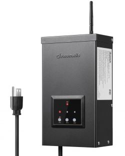
This is a low-voltage transformer for use in outdoor LED lighting etc (Product page or Amazon), with "smart" integration with Alexa and Google Assistant. It provides 3 separate zones with 12V or 14V output.
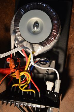
It also features power consumption measurement via a current transformer attached to the line voltage input.
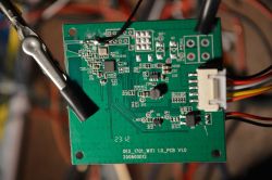
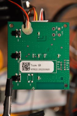
The mainboard has the following components:
The SoC pins are connected as follows (incomplete):
There is a 5-pin JST XH connector, with a ribbon cable going to the AC module.
Its pinout is as follows:
There are pin header holes for two serial ports plus the CEN pin, helpfully marked on the board.
J5 is the header for UART1 that is used for flashing.
The board can be powered via the JST connector (9VDC seems to work). It is also possible to solder a screw terminal to the large holes next to the JST connector, for easier power supply. I was also able to power it with the CHG340 USB converter.
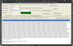
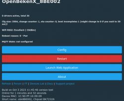
I was able to flash the OpenBK7231N_QIO_1.17.262.bin firmware with the GUI flashing tool.
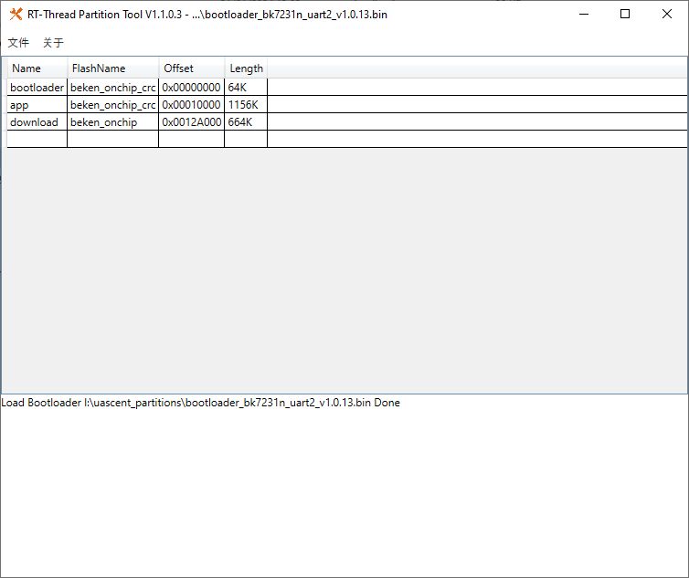
However it does not start an AP, but it does give me a command line on the serial console.
I think this is a bootloader? Using the "sta" command, it was able to connect to my WiFi, but I'm stuck at this point.


It also features power consumption measurement via a current transformer attached to the line voltage input.
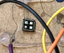
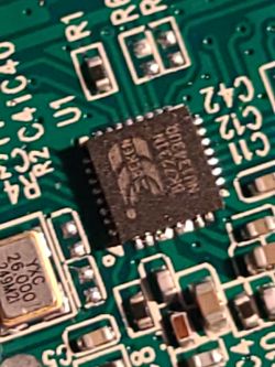
The mainboard has the following components:
| Label | Marking | Component | Role |
| U1 | BK7231N | Beken 7231N | WiFi SoC |
| U4 | AS037z | MT1470 AS037z | step-down converter |
| U5 | 321 | LM321 op-amp | for CT sensor |
| D11 | MB6S | bridge rectifier | for CT sensor |
| L4 | 6R8 | power inductor | |
| Y1 | YXC 26.000 249M2I | 26 MHz crystal | |
| D5 | LED (red) | Zone 1 LED | |
| D6 | LED (green) | WiFi LED | |
| D7 | LED (red) | Zone 2 LED | |
| D9 | LED (red) | Zone 3 LED | |
| SW4 | push button | Zone 1 switch | |
| SW3 | push button | Zone 2 switch | |
| SW2 | push button | Zone 3 switch |
The SoC pins are connected as follows (incomplete):
| P15 | SW4 | Zone 1 button |
| P16 | SW3 | Zone 2 button |
| P14 | SW2 | Zone 3 button |
| P23/ADC3 | LM321 output | CT sensor reading |
| P21 | Zone 1 relay | Active HIGH |
| P20 | Zone 2 relay | Active HIGH |
| P6 | Zone 3 relay | Active HIGH |
| P26 | WiFi LED |
There is a 5-pin JST XH connector, with a ribbon cable going to the AC module.
Its pinout is as follows:
| 1 | Zone 1 relay |
| 2 | GND |
| 3 | Vcc IN (from transformer, probably ~15V) |
| 4 | Zone 2 relay |
| 5 | Zone 3 relay |
There are pin header holes for two serial ports plus the CEN pin, helpfully marked on the board.
J5 is the header for UART1 that is used for flashing.
The board can be powered via the JST connector (9VDC seems to work). It is also possible to solder a screw terminal to the large holes next to the JST connector, for easier power supply. I was also able to power it with the CHG340 USB converter.
I was able to flash the OpenBK7231N_QIO_1.17.262.bin firmware with the GUI flashing tool.
However it does not start an AP, but it does give me a command line on the serial console.
I think this is a bootloader? Using the "sta" command, it was able to connect to my WiFi, but I'm stuck at this point.


