About The Device
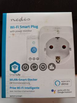
Nedis Wi-Fi Smart Plug WIFIP121FWT, Remote controllable plug with energy monitoring.
Disassembled
The plug itself
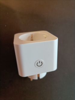
To remove the bottom cover, there is need only for simple small screw driver. The cover has small fastener in the each corner of the cover. A bit force is needed, but not that much there is any fear of breaking the cover.
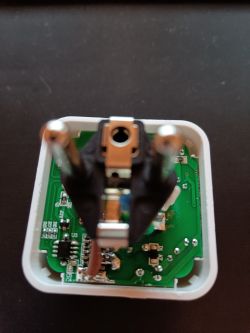
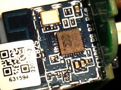
There seems to be CB2S BK7231N inside the plug
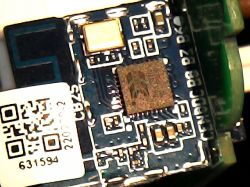
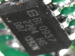
And the energy monitorig chip is BL0937
Flasing
Since I am not electronics guy, I couldn't find regulator from the PCB. There might be, but I went through all chips which I found and none of them were regulator for my eyes. So I used normal FTDI USB to TTL adapter. I soldered short cables to the 3.3V, GND, TX, RX and CEN pins of the BK7231N module.
Connected everything like this:
Fetched the binary from:
https://github.com/openshwprojects/OpenBK7231T_App
Flasher from:
https://github.com/OpenBekenIOT/hid_download_py
Once done I started flasher in my linux machine and connected the CEN pin to GND for 1seconds.
uartprogram ~/Downloads/OpenBK7231N_QIO_1.14.1.bin -d /dev/ttyUSB0 --unprotect -w --startaddr 0x0
And the result was this:
UartDownloader....
programm....
Gotten Bus... : | |[ ?k/s]caution: ignoring unexpected reply in SetBaudRate
Write Successful: |##################################################|[ 16.8k/s]
Pinout
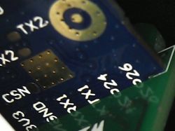
Before assembling everything back I used multimeter to check where the pins are connected from module to energy monitoring chip. Other pins were a bit tough for me so I decided to test those in the configuration.
BL0937 pin 7 (CF1) was not connected to anywhere.
Job done
Once the work was done. I removed the wires from the module and plugged in the just flashed plug. Connected to the plug with phone and changed proper SSID and PSK for it.
Then rebooted it and connected to it from my desktop and everything seems to be working so far.
Configuration
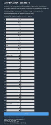
Tested where the relay is connected (not TX1 which I assume would be pin 11, and pin 26 since those are energy monitor chip). Found out that relay starts to give nice sound when configured to P8. LED started to work at P6.
Then configured 11 to be BL0937SEL and 26 to BL0937CF
The problem
The relay works so the plug can be remotely controlled. Unfortunately the BL0937 is not automatically starting up during reboot. When using command startDriver BL0937 the chip seems to be available, but once trying to give VoltageSet etc.. there is just information:
Info:EnergyMeter:VoltageSet: you gave 230.000000, set ref to inf
The index page seems like this after the VoltageSet (or after any BL0937 command)
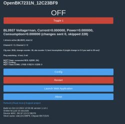
Any tips are welcome to continue from this.
Thanks a lot!
Nedis Wi-Fi Smart Plug WIFIP121FWT, Remote controllable plug with energy monitoring.

Disassembled
The plug itself

To remove the bottom cover, there is need only for simple small screw driver. The cover has small fastener in the each corner of the cover. A bit force is needed, but not that much there is any fear of breaking the cover.

There seems to be CB2S BK7231N inside the plug

And the energy monitorig chip is BL0937

Flasing
Since I am not electronics guy, I couldn't find regulator from the PCB. There might be, but I went through all chips which I found and none of them were regulator for my eyes. So I used normal FTDI USB to TTL adapter. I soldered short cables to the 3.3V, GND, TX, RX and CEN pins of the BK7231N module.
Connected everything like this:
| Module | USB to TTL |
| 3.3V | 3.3V |
| GND | GND |
| TX | RX |
| RX | TX |
Fetched the binary from:
https://github.com/openshwprojects/OpenBK7231T_App
Flasher from:
https://github.com/OpenBekenIOT/hid_download_py
Once done I started flasher in my linux machine and connected the CEN pin to GND for 1seconds.
uartprogram ~/Downloads/OpenBK7231N_QIO_1.14.1.bin -d /dev/ttyUSB0 --unprotect -w --startaddr 0x0
And the result was this:
UartDownloader....
programm....
Gotten Bus... : | |[ ?k/s]caution: ignoring unexpected reply in SetBaudRate
Write Successful: |##################################################|[ 16.8k/s]
Pinout
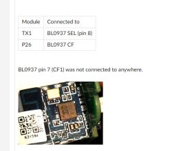
Before assembling everything back I used multimeter to check where the pins are connected from module to energy monitoring chip. Other pins were a bit tough for me so I decided to test those in the configuration.
| Module | Connected to |
| TX1 | BL0937 SEL (pin 8) |
| P26 | BL0937 CF |
BL0937 pin 7 (CF1) was not connected to anywhere.


Job done
Once the work was done. I removed the wires from the module and plugged in the just flashed plug. Connected to the plug with phone and changed proper SSID and PSK for it.
Then rebooted it and connected to it from my desktop and everything seems to be working so far.
Configuration
Tested where the relay is connected (not TX1 which I assume would be pin 11, and pin 26 since those are energy monitor chip). Found out that relay starts to give nice sound when configured to P8. LED started to work at P6.
Then configured 11 to be BL0937SEL and 26 to BL0937CF

The problem
The relay works so the plug can be remotely controlled. Unfortunately the BL0937 is not automatically starting up during reboot. When using command startDriver BL0937 the chip seems to be available, but once trying to give VoltageSet etc.. there is just information:
Info:EnergyMeter:VoltageSet: you gave 230.000000, set ref to inf
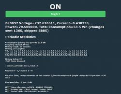
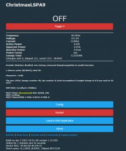
The index page seems like this after the VoltageSet (or after any BL0937 command)

Any tips are welcome to continue from this.
Thanks a lot!
Cool? Ranking DIY


