logo elektroda
logo elektroda
X
logo elektroda

BW-LT30, a WiFi adapter for a light bulb - test, teardown and ESP firmware uploa

p.kaczmarek2 7482 6
ADVERTISEMENT
Treść została przetłumaczona polish » english Zobacz oryginalną wersję tematu
  • BW-LT30, a WiFi adapter for a light bulb - test, teardown and ESP firmware uploa
    Hello my dears
    I will present here a short test of the E27-E27 adapter with WiFi from BlitzWolf, which allows you to remotely control any bulb with an E27 thread through our home WiFi network.
    In addition, in the topic I will show what exactly the WiFi module is used inside and how we can easily program it via the Arduino IDE.

    Related Topics
    I have tested these types of products before. In the first topic of the series, I gave a detailed description of the installation of a similar gadget from Blitzwolf:
    Electrical socket controlled by WiFi - BW-SHP8 - start-up and tests
    In this topic, I discussed the BlitzWolf light switch:
    Test and interior of the BW-SS3, a WiFi light switch from Blitzwolf
    And here I discussed a similar gadget from eWeLink/Coolkit:
    Socket/plug with WiFi PS-16-M and eWeLink/Coolkit application - test and teardown

    Purchased BW-LT30
    I found the BW-LT30 on the Internet for $ 11.89 + $ 2.5 shipping (about PLN 55):
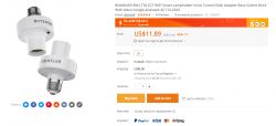
    BW-LT30, a WiFi adapter for a light bulb - test, teardown and ESP firmware uploa
    The shipment arrived quite late. I placed the order on September 13 and the courier (at least the courier) delivered the package to my hands on October 12, of course in a foil envelope with the logo of the website where I bought the item.
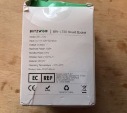
    Inside the package was a standard Blitzwolf box, albeit in a somewhat distressing condition:
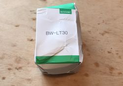
    BW-LT30, a WiFi adapter for a light bulb - test, teardown and ESP firmware uploa
    BW-LT30, a WiFi adapter for a light bulb - test, teardown and ESP firmware uploa
    There was also the usual short instructions inside:
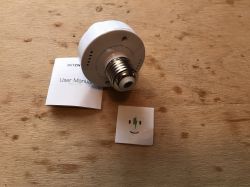
    BW-LT30, a WiFi adapter for a light bulb - test, teardown and ESP firmware uploa
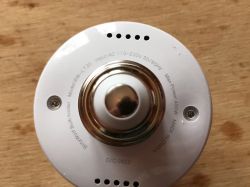
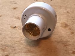
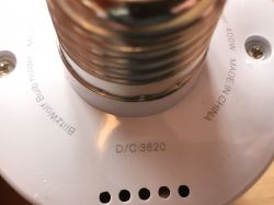
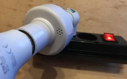
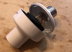
    Fortunately, the adapter itself looked untouched:
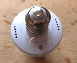
    BW-LT30, a WiFi adapter for a light bulb - test, teardown and ESP firmware uploa BW-LT30, a WiFi adapter for a light bulb - test, teardown and ESP firmware uploa BW-LT30, a WiFi adapter for a light bulb - test, teardown and ESP firmware uploa BW-LT30, a WiFi adapter for a light bulb - test, teardown and ESP firmware uploa
    The button immediately catches the eye, after all, it is a classic tactile switch and it can be seen from the outside. Shouldn't there be some kind of cap on it, a rubber band? But from the pictures on the internet it seems that no...
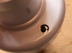
    BW-LT30, a WiFi adapter for a light bulb - test, teardown and ESP firmware uploa

    Pairing the BW-LT30 with the app
    The first connection (pairing) of the BW-LT30 with the BlitzWolf Android application was made similarly to the previous tested devices. First, I connected the lamp holder to the power supply (I used an adapter from the socket to the E27 thread):
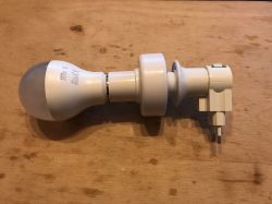
    BW-LT30, a WiFi adapter for a light bulb - test, teardown and ESP firmware uploa
    Then, in the app on my phone, I used "Manual Add" and selected "WiFi Lighting" from the "Lighting" category in the menu:
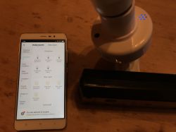
    BW-LT30, a WiFi adapter for a light bulb - test, teardown and ESP firmware uploa
    The application has already remembered my WiFi network information (SSID and password):
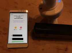
    BW-LT30, a WiFi adapter for a light bulb - test, teardown and ESP firmware uploa
    I turned the device on and off (with the button on it) several times, according to the instructions:
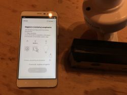
    BW-LT30, a WiFi adapter for a light bulb - test, teardown and ESP firmware uploa
    This caused the LED on the device to flash:
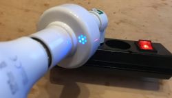
    BW-LT30, a WiFi adapter for a light bulb - test, teardown and ESP firmware uploa BW-LT30, a WiFi adapter for a light bulb - test, teardown and ESP firmware uploa
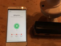
    I checked the "Confirm blinking" box, clicked "Next" and the rest of the pairing was successful by itself:
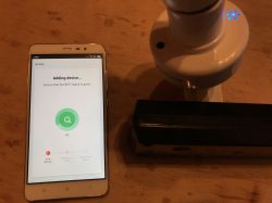
    BW-LT30, a WiFi adapter for a light bulb - test, teardown and ESP firmware uploa BW-LT30, a WiFi adapter for a light bulb - test, teardown and ESP firmware uploa
    BW-LT30, a WiFi adapter for a light bulb - test, teardown and ESP firmware uploa
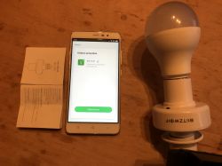
    Since then, the device has appeared in my list of Blitzwolf devices:
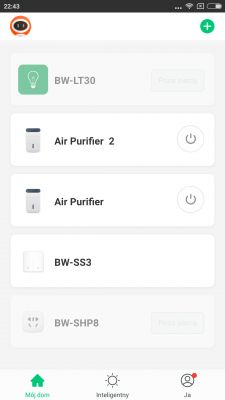
    BW-LT30, a WiFi adapter for a light bulb - test, teardown and ESP firmware uploa

    Interior of the BW-LT30
    BW-LT30 started and checked, now it's time for teardown.
    We get inside by unscrewing two screws, these here:
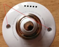
    BW-LT30, a WiFi adapter for a light bulb - test, teardown and ESP firmware uploa
    However, this is not enough to remove the board:
    BW-LT30, a WiFi adapter for a light bulb - test, teardown and ESP firmware uploa
    You still need to loosen the two screws that hold the wires to the frame from the inside:
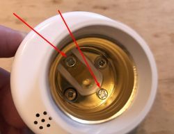
    BW-LT30, a WiFi adapter for a light bulb - test, teardown and ESP firmware uploa
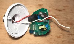
    After loosening them, you can gently pull out (and slightly twist) the electronics board. From the inside it looks like this:
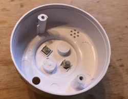
    BW-LT30, a WiFi adapter for a light bulb - test, teardown and ESP firmware uploa
    other half:
    BW-LT30, a WiFi adapter for a light bulb - test, teardown and ESP firmware uploa
    Then you can look at the plate.
    BW-LT30, a WiFi adapter for a light bulb - test, teardown and ESP firmware uploa
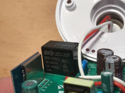
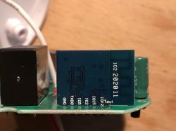
    The relay JZC-32F 005-HSQ (10A 250V) immediately catches the eye. The heart of the system is also immediately visible, i.e. the WiFi module with an antenna on the PCB:
    BW-LT30, a WiFi adapter for a light bulb - test, teardown and ESP firmware uploa
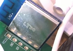
    On the cover of the WiFi module there is only the name of the whole device - LT30:
    BW-LT30, a WiFi adapter for a light bulb - test, teardown and ESP firmware uploa
    So it's not sure what kind of module it is, but it looks like an ESP8266 (often used in this type of devices). This is also suggested by the pins signed on his board (GND, TXD0, IO5, IO2, IO15, Tout).
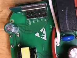
    In addition, soldering points (VCC33V, GND, IO0, TX, RX) are signed next to it, which look like a programming connector:
    BW-LT30, a WiFi adapter for a light bulb - test, teardown and ESP firmware uploa
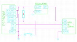
    What we see here is consistent with the description available on the web of how to program the ESP8266 via UART:
    BW-LT30, a WiFi adapter for a light bulb - test, teardown and ESP firmware uploa
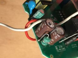
    On top of the board you can also see 4.7uF 400V capacitors, a choke:
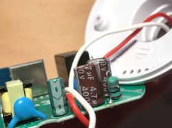
    BW-LT30, a WiFi adapter for a light bulb - test, teardown and ESP firmware uploa BW-LT30, a WiFi adapter for a light bulb - test, teardown and ESP firmware uploa
    You can also see a small transformer, so there is probably a small impulse power supply on board.
    As well as the element signed "F1", probably from Fuse (fuse / fuse resistor) and VR1 (varistor):
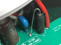
    BW-LT30, a WiFi adapter for a light bulb - test, teardown and ESP firmware uploa
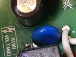
    Close-up of the varistor:
    BW-LT30, a WiFi adapter for a light bulb - test, teardown and ESP firmware uploa
    Nearby there is also a similar in color but completely different in function element CY1, a capacitor with code 102 (i.e. 1nF value) connecting the primary side of the converter with its secondary side:
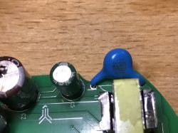
    BW-LT30, a WiFi adapter for a light bulb - test, teardown and ESP firmware uploa
    There are a lot of SMD components on the bottom.
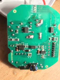
    BW-LT30, a WiFi adapter for a light bulb - test, teardown and ESP firmware uploa
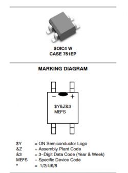
    First of all, the MB6S mains voltage rectifier bridge in the SOIC4 housing:
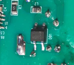
    BW-LT30, a WiFi adapter for a light bulb - test, teardown and ESP firmware uploa
    BW-LT30, a WiFi adapter for a light bulb - test, teardown and ESP firmware uploa
    His datasheet for those interested:
    MB8S-D.PDF Download (345.88 kB)
    A little further behind it is the THX208:
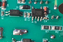
    BW-LT30, a WiFi adapter for a light bulb - test, teardown and ESP firmware uploa
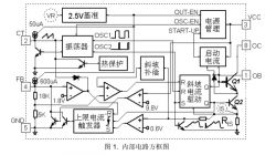
    This is the PWM controller of the converter, i.e. the system on which the module is powered from the ESP. It creates a small switched-mode power supply that runs all the time as soon as the BW-LT30 is connected to the mains.
    Its output can be found on the Internet:
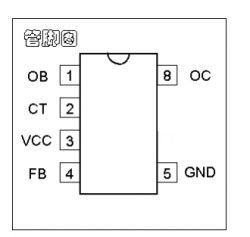
    BW-LT30, a WiFi adapter for a light bulb - test, teardown and ESP firmware uploa
    internal diagram:
    BW-LT30, a WiFi adapter for a light bulb - test, teardown and ESP firmware uploa
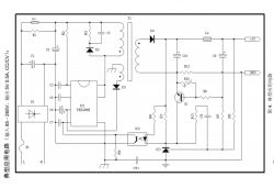
    Example application:
    BW-LT30, a WiFi adapter for a light bulb - test, teardown and ESP firmware uploa
    The example diagram from THX208 tells us what we can find on the board a bit further - there should be an optocoupler there, and it is in fact:
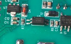
    BW-LT30, a WiFi adapter for a light bulb - test, teardown and ESP firmware uploa
    Full THX208 data sheet:
    THX208.pdf Download (804.5 kB)
    JC3H7 is just an optocoupler. It looks like the more famous one
    JC817:
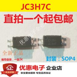
    BW-LT30, a WiFi adapter for a light bulb - test, teardown and ESP firmware uploa
    Also nearby are the rectifier diodes required for the THX208 to function:
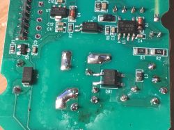
    BW-LT30, a WiFi adapter for a light bulb - test, teardown and ESP firmware uploa
    In addition, there is also AMS1117 3.3, which is an LDO regulator providing a stable 3.3V for ESP:
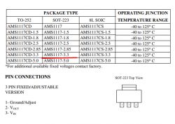
    BW-LT30, a WiFi adapter for a light bulb - test, teardown and ESP firmware uploa
    In addition, on the board we see one small transistor that simply turns on/off the relay and is controlled directly from the GPIO from ESP.

    Continuation of teardown - the center of the WiFi module
    The subject could be finished, but for me it was a bit too much.
    I decided that it would be worth checking what is really in the WiFi module.
    First, I just soldered the programming pins:
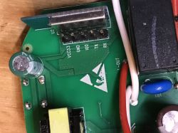
    BW-LT30, a WiFi adapter for a light bulb - test, teardown and ESP firmware uploa
    But then I decided that I would not guess what kind of ESP is inside (although I know that it would be possible without it) and I just decided to desolder it from the board with a braid:
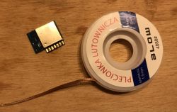
    BW-LT30, a WiFi adapter for a light bulb - test, teardown and ESP firmware uploa
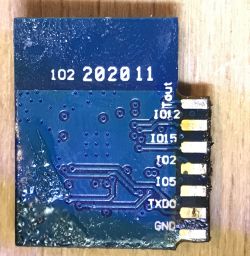
    After desoldering, I saw that its pins on the other side are signed - it will come in handy for sure . Before desoldering, it was covered by a laminate.
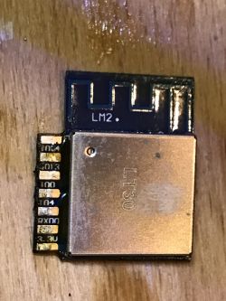
    BW-LT30, a WiFi adapter for a light bulb - test, teardown and ESP firmware uploa
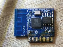
    I also took off its cover:
    BW-LT30, a WiFi adapter for a light bulb - test, teardown and ESP firmware uploa
    BW-LT30, a WiFi adapter for a light bulb - test, teardown and ESP firmware uploa
    My initial suspicions were confirmed. It's an ESP8266, along with a 26MHz clock and a BoyaMicro Flash memory chip.

    Communication with the WiFi module
    ESP8266 programming is done via UART. ESP8266 requires 3.3V (not 5V!) power supply for proper operation and connecting GPIO0 to ground during programming. As in this diagram:
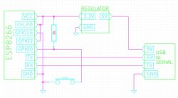
    BW-LT30, a WiFi adapter for a light bulb - test, teardown and ESP firmware uploa
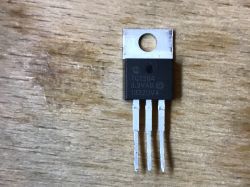
    As a 3.3V regulator I used TC1264:
    BW-LT30, a WiFi adapter for a light bulb - test, teardown and ESP firmware uploa
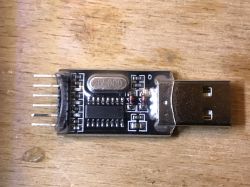
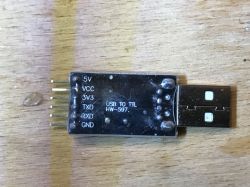
    And as a USBUART HW-597 converter:
    BW-LT30, a WiFi adapter for a light bulb - test, teardown and ESP firmware uploa BW-LT30, a WiFi adapter for a light bulb - test, teardown and ESP firmware uploa
    I assembled everything on the breadboard.
    I soldered the cables to the desoldered module (only soldered GND, RX, TX, VCC3.3V and GPIO0) and connected it to the 3.3V power supply and the UART converter:
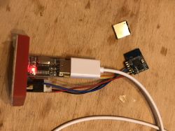
    BW-LT30, a WiFi adapter for a light bulb - test, teardown and ESP firmware uploa
    On the desktop side, I used XTCOM_UTILITY:
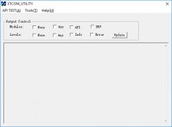
    BW-LT30, a WiFi adapter for a light bulb - test, teardown and ESP firmware uploa
    Just in case, I give XTCOM_UTILITY in the attachment below:
    ESP8266-XT...M_UTIL.zip Download (183.8 kB)
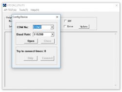
    In Tools->Config Device, I chose the COM port setting (for me it was COM3, standard baud as for ESPs 115200):
    BW-LT30, a WiFi adapter for a light bulb - test, teardown and ESP firmware uploa
    (It is worth noting here that XTCOM_UTILITY has fixed COM ports from 1 to 6 and does not see other ports, and our adapter may have a larger number, e.g. COM15. Then you need to change its COM number in the device manager to something from 1 to 6.)
    I clicked Open - opening the COM port was successful:
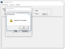
    BW-LT30, a WiFi adapter for a light bulb - test, teardown and ESP firmware uploa
    (at this point we don't know yet if we have communication with ESP)
    And then I clicked "Connect" to see if ESP is responding to our packets:
    BW-LT30, a WiFi adapter for a light bulb - test, teardown and ESP firmware uploa
    Success! So the communication with the ESP was successful and it can now be programmed.
    But I didn't program ESP via XTCOM_UTILITY, I thought there was a better way...

    The first attempt to program the ESP8266 module with Arduino
    I wanted to program the ESP8266 with the simplest possible program, i.e. 'blinking the diode' only to check if everything is functional.
    I used the Arduino IDE, which supports ESP8266 (and similar) after adding the appropriate package from Github:
    https://github.com/esp8266/Arduino
    It is added via 'Board Manager', details in git repository above.
    A copy of the repository version used:
    ESP-Arduin...-10-13.zip Download (39.17 MB)
    I also had to connect a diode. I chose GPIO2 (pin 2, it was also selected in Arduino by default) and soldered a cable to it:
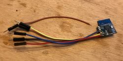
    BW-LT30, a WiFi adapter for a light bulb - test, teardown and ESP firmware uploa
    In addition, I added a 470 ohm resistor and an LED to my breadboard.
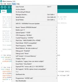
    In Arduino, I selected "Generic ESP8266 Module", baud 115200:
    BW-LT30, a WiFi adapter for a light bulb - test, teardown and ESP firmware uploa
    I compiled and uploaded the blink code from 'Examples':
    Code: C / C++
    Log in, to see the code

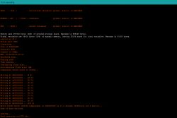
    The upload was successful, here is the full log:
    BW-LT30, a WiFi adapter for a light bulb - test, teardown and ESP firmware uploa
    However, the LED did not start flashing. I had to first disconnect the GPI0 from ground and turn it off and reconnect the system to the power supply. Result:


    Finally, I modified the blink a bit:
    Code: C / C++
    Log in, to see the code

    Result:


    Everything seems to be working. You still need to check more advanced things (WiFi) and also check the programming of this ESP in the entire BW-LT30 adapter, but that's another time.

    Summary
    The product is functional and fulfills its role correctly, although I have the impression that it is a bit more crude than its other counterparts available on the web. It also seems to be quite large and I think that if the manufacturer tried, it could minimize everything a bit more.
    However, the method of connecting the BW-LT30 has one very strong side, namely it can be installed by anyone who can screw in/unscrew a light bulb. It is certainly easier than, for example, replacing a light switch from a box with a 'smart' one (e.g. as discussed here) .
    In the subject, I also checked what is really in this BW-LT30, especially since I did not find information about it in the search engine. I don't think anyone checked it before, because I didn't see the BW-LT30 on the list of supported devices by Tasmota and the like.
    And inside, of course, there is an ESP8266 and it can be easily programmed, so nothing stands in the way of uploading your own firmware there.
    In addition, I checked how we can write code for it - everything can be easily done in the Arduino IDE. Setting up the environment for this takes literally a few minutes and I think that really anyone can blink the LED themselves through such an ESP.
    PS: Now I still have to solder this module with ESP8266 back inside, but maybe I'll deal with that soon - I'm still planning to make a 'collective topic' on the forum about uploading my own firmware (Tasmota? Domoticz?) to this type of products like the one presented here, but I'll write about that another time.

    Cool? Ranking DIY
    Helpful post? Buy me a coffee.
    Do you have a problem with Arduino? Ask question. Visit our forum Arduino.
    About Author
    p.kaczmarek2
    Moderator Smart Home
    Offline 
    p.kaczmarek2 wrote 11927 posts with rating 9987, helped 572 times. Been with us since 2014 year.
  • ADVERTISEMENT
  • #2 18976555
    ArturAVS
    Moderator
    p.kaczmarek2 wrote:
    As well as the element signed "F1", probably from Fuse (fuse / fuse resistor) and VR1 (interference suppression capacitor):

    F1 is the fuse, VR1 is the varistor (surge protection).
  • ADVERTISEMENT
  • #3 18976663
    p.kaczmarek2
    Moderator Smart Home
    ArturAVS wrote:
    p.kaczmarek2 wrote:
    As well as the element signed "F1", probably from Fuse (fuse / fuse resistor) and VR1 (interference suppression capacitor):

    F1 is the fuse, VR1 is the varistor (surge protection).


    Thank you, I corrected. VR1 somehow reminded me visually of CY1 (also on this board), this 1nF capacitor connecting the primary and secondary sides of the converter and I mistakenly treated these elements as one.

    The topic will still be completed, I will add information on which ESP pin is the relay, and on which is the diode.
    Helpful post? Buy me a coffee.
  • ADVERTISEMENT
  • #4 18977629
    khoam
    Level 42  
    p.kaczmarek2 wrote:
    It's an ESP8266, along with a 26MHz clock and a BoyaMicro Flash memory chip.

    It would be a good idea to check what size this Flash memory is. It is difficult to read its marking from the picture.
  • ADVERTISEMENT
  • #5 18977729
    p.kaczmarek2
    Moderator Smart Home
    khoam wrote:

    It would be a good idea to check what size this Flash memory is.


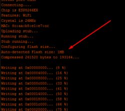
    I noticed this, but I was suggested by the message from the Arduino IDE:
    BW-LT30, a WiFi adapter for a light bulb - test, teardown and ESP firmware uploa
    and I found that it correctly detects itself.

    But OK:
    BW-LT30, a WiFi adapter for a light bulb - test, teardown and ESP firmware uploa BW-LT30, a WiFi adapter for a light bulb - test, teardown and ESP firmware uploa
    25Q80BSTIG, I think 25Q80BSIG.
    BW-LT30, a WiFi adapter for a light bulb - test, teardown and ESP firmware uploa
    This would be consistent with what has been discovered...
    Helpful post? Buy me a coffee.
  • #6 18977821
    khoam
    Level 42  
    Flash 1MB for ESP8266 is the minimum. You can upload ESPEasy, Tasmota or ESPurna. You can also experiment with Blynk.

    Added after 20 [minutes]:

    p.kaczmarek2 wrote:
    I had to first disconnect the GPI0 from ground and turn it off and reconnect the system to the power supply.

    If GPIO 0 is connected to ground, the ESP8266 is in bootloader mode, i.e. it is waiting for the program to be uploaded.
  • #7 18983146
    krzbor
    Level 27  
    khoam wrote:
    Flash 1MB for ESP8266 is the minimum. You can upload ESPEasy, Tasmota or ESPurna. You can also experiment with Blynk.
    You can also update via OTA. With 512kB it is not possible, at least in the case of Arduino, where the project is about 360kB, and both versions (old and downloaded) must be in memory at the time of loading.

Topic summary

The discussion centers around the BW-LT30, a WiFi adapter for E27 light bulbs from BlitzWolf, which allows remote control of bulbs via a home WiFi network. The user shares insights from a test and teardown of the device, including details about the internal WiFi module and programming it using the Arduino IDE. Participants discuss components such as the fuse (F1), varistor (VR1), and the importance of Flash memory size for the ESP8266 chip, noting that a minimum of 1MB is required for uploading firmware like ESPEasy, Tasmota, or ESPurna. The conversation also touches on the bootloader mode for programming and the possibility of OTA updates, emphasizing the limitations of 512kB memory for larger projects.
Summary generated by the language model.
ADVERTISEMENT