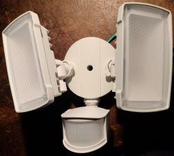
This is a motion-activated outdoor LED floodlight.

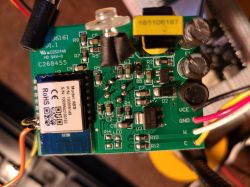
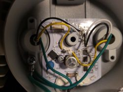
It features a W3BS module, two CW LED lights, a PIR motion sensor, and an ambient light sensor.


I was able to solder wires to the RX1 and TX1 pins on the module (as in the photo). The four wires in the lower right (VCE, GND, W, C) lead to a JST connector on the other board. I unplugged this and connected VCE and GND (9V worked, this goes to the AMS1117 regulator). The GND pin of the USB serial adapter was connected to the common ground with the power supply, and the 3.3V pin on the USB adapter was not used.
I didn't succeed in flashing with the GUI flasher (got stuck immediately on reading 0x00), but was able to flash using "uartprogram" from hid_download.
The SoC pins are connected as follows:
The motion sensor goes HIGH when motion is detected. The ambient light sensor readings range from 0 (brightest) to 3000 (darkest).
My configuration is as follows:
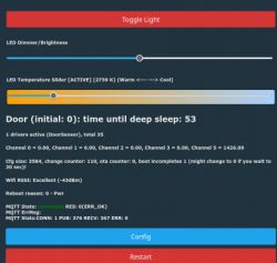
This allows me to control the brightness and color temperature with the two PWM channels (CW mode).

A few outstanding questions:
* How to tie the two CW LED channels to the motion sensor. If I assign the motion sensor to one of the LED channels, then the sensor only controls that LED and not the other, giving the wrong color temperature.
* How to add a time delay so that the light stays on for some time after motion is detected.
* The original firmware offers the possibility of adjusting the sensitivity of the motion sensor (four levels). I haven't figured out how this works.
I can program this control logic in my openHAB installation, but would rather have the device handle it autonomously.

It features a W3BS module, two CW LED lights, a PIR motion sensor, and an ambient light sensor.


I was able to solder wires to the RX1 and TX1 pins on the module (as in the photo). The four wires in the lower right (VCE, GND, W, C) lead to a JST connector on the other board. I unplugged this and connected VCE and GND (9V worked, this goes to the AMS1117 regulator). The GND pin of the USB serial adapter was connected to the common ground with the power supply, and the 3.3V pin on the USB adapter was not used.
I didn't succeed in flashing with the GUI flasher (got stuck immediately on reading 0x00), but was able to flash using "uartprogram" from hid_download.
The SoC pins are connected as follows:
| P6 | Motion sensor |
| P8 | LED (cool) |
| P9 | LED (warm) |
| P23/ADC3 | Ambient light sensor |
The motion sensor goes HIGH when motion is detected. The ambient light sensor readings range from 0 (brightest) to 3000 (darkest).
My configuration is as follows:
{
  "vendor": "UME",
  "bDetailed": "0",
  "name": "Tuya Smart LED Outdoor Security Floodlight",
  "model": "N/A",
  "chip": "BK7231T",
  "board": "TODO",
  "flags": "1024",
  "keywords": [
    "TODO",
    "TODO",
    "TODO"
  ],
  "pins": {
    "6": "dInput_NoPullUp;3",
    "8": "Rel;1",
    "9": "Rel;2",
    "23": "ADC;5"
  },
  "command": "",
  "image": "https://obrazki.elektroda.pl/2082550400_1696896808.jpg",
  "wiki": "https://www.elektroda.com/rtvforum/topic4007225.html"
}
This allows me to control the brightness and color temperature with the two PWM channels (CW mode).

A few outstanding questions:
* How to tie the two CW LED channels to the motion sensor. If I assign the motion sensor to one of the LED channels, then the sensor only controls that LED and not the other, giving the wrong color temperature.
* How to add a time delay so that the light stays on for some time after motion is detected.
* The original firmware offers the possibility of adjusting the sensitivity of the motion sensor (four levels). I haven't figured out how this works.
I can program this control logic in my openHAB installation, but would rather have the device handle it autonomously.


