logo elektroda
logo elektroda
X
logo elektroda

AUBESS 20A 230V WIFI socket based on BK7231N - How to configure?

jmalko 966 5
ADVERTISEMENT
Treść została przetłumaczona polish » english Zobacz oryginalną wersję tematu
  • #1 21101120
    jmalko
    Level 8  
    Hello there,
    I have such a socket as in the title I managed to rip the old software using BKWriter and BK7231 Easy Uart. They differ a bit and it looks as if this software from BKWriter is incomplete despite setting the start and end address. With Easy Uart I flashed the software and it immediately backed up and displayed the configuration. I'm at the stage where I have the configuration I'm in the panel at 192.168.4.1 and I don't know how to set the pins correctly because the names from the configuration don't quite match the one in the panel. I am uploading two of my screenshots as an attachment.

    {
    	"sel_pin_pin":"24",
    	"rl1_lv":"1",
    	"bt1_pin":"23",
    	"net_trig":"4",
    	"jv":"1.0.5",
    	"netled1_lv":"0",
    	"netled_reuse":"1",
    	"bt1_type":"0",
    	"ffc_select":"1",
    	"vi_pin":"6",
    	"resistor":"1",
    	"over_cur":"21000",
    	"bt1_lv":"0",
    	"reset_t":"5",
    	"netled1_pin":"8",
    	"chip_type":"0",
    	"lose_vol":"0",
    	"over_vol":"0",
    	"module":"CB2S",
    	"ele_pin":"7",
    	"ch_cddpid1":"9",
    	"ch1_stat":"0",
    	"rl1_type":"0",
    	"ch_num":"1",
    	"ele_fun_en":"1",
    	"rl1_pin":"26",
    	"vol_def":"0",
    	"ch_dpid1":"1",
    	"sel_pin_lv":"1",
    	"crc":"32"
    }
    .
    
    Device configuration, as extracted from Tuya: 
    - BL0937 SEL on P24
    - Button (channel 1) on P23
    - BL0937 VI on P6
    - WiFi LED on P8
    - BL0937 ELE on P7
    - Relay (channel 1) on P26
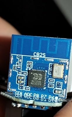
    Device seems to be using CB2S module, which is using BK7231N.
    And the Tuya section starts at UNCOMMON POSITION 1953792
    .
    I would appreciate your guidance on what to do next with this configuration.

    Kind regards.
  • ADVERTISEMENT
  • Helpful post
    #2 21101136
    p.kaczmarek2
    Moderator Smart Home
    bkWriter 1.60 is not recommended, when uploading a 2MB batch it can damage the bootloader, as it loops the address (starts uploading at offset 0x11000 and then loops at 2MB and overwrites previous bytes).
    bkWriter 1.60 by default does not take a 2MB batch, you have to artificially enter a length of 2 megabytes, but even so, this is not recommended.
    We now use:
    https://github.com/openshwprojects/BK7231GUIFlashTool

    As you are in AP mode, you should first configure WiFi and connect the socket to your router. Only then can you upload the template.

    The template is uploaded automatically. You do not need to enter it manually. Here you are shown how to import]:


    .
    It is worth noting that the Web App will rather work when connected to your WiFi (unless your machine has a separately connected internet...).
    You can also paste Tuya's JSON directly into that field from the video, which is what you already put in the post.


    PS: Can you show what exact socket you have, what model, where bought, etc, so I can add it to our list here: https://openbekeniot.github.io/webapp/devicesList.html
    Helpful post? Buy me a coffee.
  • ADVERTISEMENT
  • #3 21101556
    jmalko
    Level 8  
    Of course I'm going to share the information, especially as I want to put together a YouTube video of it and show what a brilliant project there is.
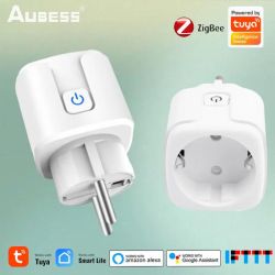
    The socket is called AUBESS 20A 230V and was bought still on Shopee for a pittance, maybe £15.
    AUBESS 20A 230V WIFI socket based on BK7231N - How to configure? .
    Image photo from Aliexpress.

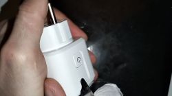
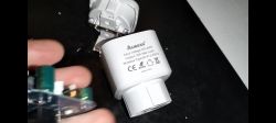
    A person holds a white smart plug with a socket, featuring a side power button. Image of an AUBESS 20A 230V smart plug with visible specification label. Hand holding a white AUBESS electric socket. .
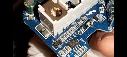
    SoC: BK7321N
    The circuit for measuring power consumption is BL0937
    Close-up of the AUBESS 20A 230V circuit board with visible components and integrated circuits. .
    The board is CB2S .
    Blue LED.
    Pinout
    CB2S board with BK7321N chip and electronic components. Close-up of a PCB with connector pin labels and indicators.
    The configuration in the first post is correct.

    You do not need to desolder the board! .
    The procedure to start flashing looked standard. Connect the UART adapter to the computer, install the drivers, enable the program BK7231N Easy UART , set the baudrate: 115200 , chip type: BK7231N , firmware: OpenBK7231N_QIO_1.17.592.bin , then click For firmware write on the board we short-circuit the pin for a moment. CEN with GND and all the magic begins. I won't describe the rest as it's in the above post. I hope someone finds such information useful.
    PS. I see that these sockets also appear on Aliexpress with different LED colours.
    PS2. Question for you @p.kaczmarek2: Is there somewhere a measurement of the consumed energy available from the WWW? I need to read this parameter for myself in order to make a logger and later convert into electricity cost.
    PS3. How do I adjust the LED so that it does not light up when the device is switched off, as it was in the original firmware?
  • ADVERTISEMENT
  • Helpful post
    #4 21102170
    p.kaczmarek2
    Moderator Smart Home
    I think something got messed up in the previous post.

    Which YT channel? I'd be happy to help.

    You can read this parameter in different ways. You can:
    - use the variable $energy and send it via HTTP GET to your server. Below is an example but for other variables:
    
    again:
    // send data
    SendGET http://address:port/sensor1.php?temp=$CH2&hum=$CH3&bat=$voltage
    // wait for GET to be sent
    delay_s 5
    goto again
    
    .
    - send from your client to the Tasmota style OBK the status command to retrieve the SNS status and there is the ENERGY entity
    
    http://192.168.0.163/cm?cmnd=STATUS%208
    
    .
    - send from your client to OBK the command echo $energy and read the response (but this was just added, so you need to do an update first)
    
    http://192.168.0.163/cm?cmnd=echo%20$energy
    
    .
    - write your own driver and freely send/process variables from within C: https://www.elektroda.pl/rtvforum/topic4056286.html#21095505

    Examples:
    https://github.com/openshwprojects/OpenBK7231T_App/blob/main/docs/autoexecExamples.md

    You can swap the role of the diode pin with the reverse, with the _n .
    https://github.com/openshwprojects/OpenBK7231T_App/blob/main/docs/ioRoles.md
    Helpful post? Buy me a coffee.
  • ADVERTISEMENT
  • Helpful post
    #5 21112064
    jmalko
    Level 8  

    @p.kaczmarek2 The channel is called #BehindTechnology on which I try to share my solutions to various problems. The video has already been created and can be found here


    .
    Best regards to the entire elektroda community.
  • #6 21122201
    p.kaczmarek2
    Moderator Smart Home
    Very good material, if you want, you can put it as a separate topic in the Smart Home Tips section and then Elektroda will put it on the homepage among other articles.
    Helpful post? Buy me a coffee.
ADVERTISEMENT