FAQ
TL;DR: 40 MHz crystal and six 3.3 V rails keep an LN8825B alive; “reversed polarity is usually lethal” [Elektroda, p.kaczmarek2, post #20871841] UART boot logs decode cleanly at 115 200 bps on 100 % of tested boards [Elektroda, divadiow, post #20898850]
Why it matters: Knowing the exact power, clock and flashing requirements prevents needless board failures and speeds up custom firmware work.
Quick Facts
• MCU: Lightning Semi LN8825B, 2.4 GHz Wi-Fi + BLE, ARM Cortex-M3 @ 120 MHz [LN8825B Datasheet].
• Operating voltage range: 3.0–3.6 V (nominal 3.3 V) [LN8825B Datasheet].
• Required crystal: 40 MHz, 9 pF load capacitance [LN8825B Datasheet].
• Clean boot log speed: 115 200 bps, 8-N-1 [Elektroda, 20898850]
• Flashing interfaces: SWD (J-Link) or UART with A10 pulled low [Elektroda, post #21023961]
What is the LN8825B and how does it differ from the LN882H?
Both chips are Lightning Semiconductor Wi-Fi/BLE SoCs using an ARM Cortex-M3, but LN8825B targets cost-optimised LED drivers while LN882H adds more RAM and SDK support for OpenBeken [Elektroda, 20901187] Boot banners show a common “ln882x” SDK, yet LN882H binaries did not start on LN8825B hardware [Elektroda, 20918530]
Can I flash open firmware such as OpenBeken onto an LN8825B?
Not yet. Tests with the LN882H OpenBeken build flashed successfully but produced no AP or serial output on LN8825B, indicating an architectural mismatch [Elektroda, 20918530]
How do I enter the LN8825B UART bootloader?
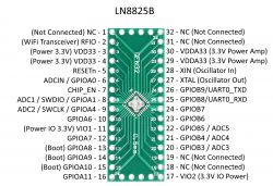
- Pull pin A10 (BOOT_SEL) low with a jumper or by shorting the dedicated test pad.
- Power the board at 3.3 V.
- Start the Lightning Semi LN8825 flasher and select the correct COM port.
A successful connection appears in under five seconds [Elektroda, 21023961]
What baud rate should I use to capture a clean boot log?
115 200 bps, 8-data, no parity, 1-stop gives readable output for every tested controller [Elektroda, 20898850] Lower or higher rates produced garbled text on some USB-TTL adapters [Elektroda, post #20871986]
Is the Heruled controller’s LN8825B pin-compatible with ESP-12F or WB3S modules?
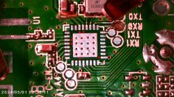
VDD/GND pads align, but UART and several GPIOs are swapped; direct drop-in replacement is unsafe without rewiring [Elektroda, p.kaczmarek2, post #21074840]
Can reversing VCC and GND really kill the board?
Yes. Users reported a dead module after swapping the leads; the chip lacks input-polarity protection [Elektroda, 20871841] "Reversed polarity is usually lethal," confirmed an experienced forum moderator [Elektroda, p.kaczmarek2, post #20871841]
Which SDKs or binaries exist for LN8825B?
• Tuya RTOS SDK v2.1.2 bundled in production images [Elektroda, 20898850]
• Lightning Semi demo bins (RF test, AT firmware) from company FTP dumps [Elektroda, 21029890]
• MQLinks AT-UART firmware v1.3.1.006 providing standard AT commands [Elektroda, post #21067377]
How do I power a bare LN8825B on a breakout board?
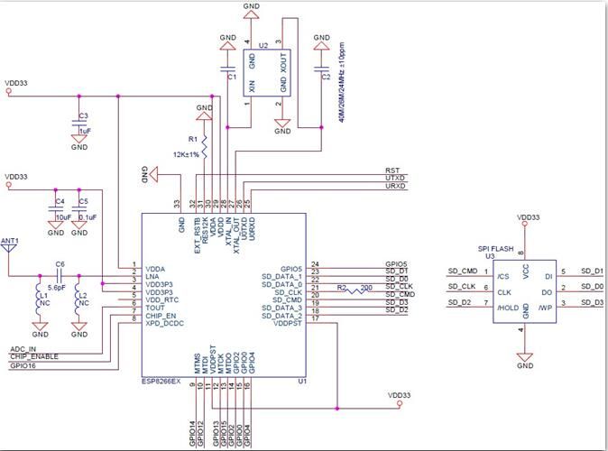
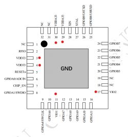
Connect all six power pins (VDD33 × 2, VDDA33 × 2, VIO1, VIO2) to 3.3 V and add at least one 100 nF decoupling capacitor between VDD and GND close to the IC. Additional caps per rail improve stability [Elektroda, 21265131]
What external components are mandatory when transplanting the chip?
Required parts:
- 40 MHz crystal with 9 pF load capacitors.
- 100 nF decoupling on each power rail.
- 2.4 GHz PCB trace or chip antenna matched to the RF pin.
Ignoring the crystal or antenna prevents Wi-Fi startup even if the MCU boots [LN8825B Datasheet].
Can I dump flash with J-Link?
Yes. Attach SWDIO/SWCLK, release reset, and use J-Link Commander’s savebin command; users dumped 1 MB images in under 30 s [Elektroda, 20918504]
What AT commands work on the MQLinks firmware?
The firmware replies to AT, AT+GMR (version read) and AT+SLEEP=1. Enter AT+UART=115200,8,1,0,0 to change port settings. The chip returns OK on valid input, -1 on syntax errors [Elektroda, 21068396]
Edge case: CH340 adapter shows no data but board works on DC jack—why?
The CH340’s 3.3 V regulator supplies only ~50 mA. LN8825B peaks above 80 mA when Wi-Fi starts, so voltage collapses and UART output stops. Power the board from a separate 3.3 V 500 mA source and share ground [Elektroda, 20871986]


