logo elektroda
logo elektroda
X
logo elektroda

How to Fix Random Relay Switching on BL602 IoT Devices with SM-028_V1.3?

pavlenkoblok 4296 19
ADVERTISEMENT
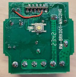
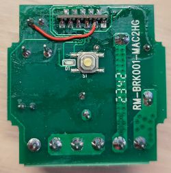
  • View of SM-028_V1.3 module PCB with BL602L20 chip. SM-028_V1.3 relay module with visible circuit board and components. SM-028_V1.3 module with BL602L20 chip on a circuit board. SM-028_V1.3 module with BL602L20 chip on a green PCB, featuring electronic components and a screw terminal. Image of SM-028_V1.3 module with BL602L20 chip showing RM-BRK001-MAC2HG marking.
    Relay based on SM-028_V1.3 module with BL602L20 chip.
    These relays have a massive problem with the fact that they randomly turn the relay on and off. In order to fix this, you need to solder components C6 0.1 uF and R1 10 kOhm.
    Close-up of a PCB showing component locations for C6 and R1.
    For firmware, I unsoldered the SM-028_V1.3 module, connected the
    SM-028|UART
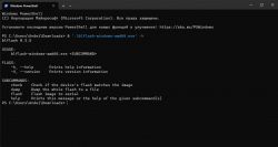
    TX--------RX
    RX--------TX
    GND-----GND
    3V3------3V
    BT--------3V module with the uart adapter, and then connected the uart adapter to the PC.
    I flashed it using the blflash program with the command '.\blflash-windows-amd64.exe' flash OpenBL602_1.17.402.bin --port COM7.
    Configuration:
    {
      "vendor": "eWelink",
      "bDetailed": "0",
      "name": "MINI Smart WI-FI switch",
      "model": "WI-FI switch",
      "chip": "BL602",
      "board": "SM-028_V1.3",
      "flags": "1024",
      "keywords": [
        "SM-028_V1.3",
        "BL602L20"
      ],
      "pins": {
        "3": "TglChanOnTgl;1",
        "14": "LED_n;1",
        "20": "Btn;1",
        "21": "Rel;1"
      },
      "command": "",
      "image": "https://obrazki.elektroda.pl/9338489200_1705009676.jpg",
      "wiki": "https://www.elektroda.com/rtvforum/viewtopic.php?p=20904492"
    }

    Cool? Ranking DIY
    About Author
    pavlenkoblok
    Level 2  
    Offline 
    pavlenkoblok wrote 2 posts with rating 4, helped 1 times. Been with us since 2023 year.
  • ADVERTISEMENT
  • #2 20904602
    p.kaczmarek2
    Moderator Smart Home
    Good tutorial. It's a shame that manufacturer tries so hardly to optimize the costs that they don't actually even want to solder those two cheap components.
    Helpful post? Buy me a coffee.
  • #3 20904710
    gulson
    System Administrator
    After all, these components cost from $0.10 with assembly, I do not understand this savings.
  • #4 20904798
    krzbor
    Level 27  
    pavlenkoblok wrote:
    To fix this, the components C6 0.1 mF and R1 10 Kom should be soldered out.
    Maybe this should be corrected, as the sentence implies that these components should be removed, not added.
  • #5 20904846
    p.kaczmarek2
    Moderator Smart Home
    By the way, I didn't even know that you can flash BL602 from the command line:
    
    .\blflash-windows-amd64.exe flash OpenBL602_1.17.402.bin --port COM7
    

    I've always used BLDevCube.exe, and here's such a surprise. I wonder if blflash-windows-amd64.exe can also read the original batch?
    Helpful post? Buy me a coffee.
  • ADVERTISEMENT
  • #6 20904939
    speedy9
    Helpful for users
    So I'm wondering if soldering these components corresponds to flashing in any way? Does soldering alone solve the relay switching problem in the original "ecosystem"?
    I have several switches under Tuya at home, and indeed some happen to change state on their own (especially to "off"). What are these two components responsible for?
  • #7 20904966
    p.kaczmarek2
    Moderator Smart Home
    speedy9 wrote:

    I have several switches under Tuya at home and indeed some happen to change state by themselves (especially to "off").
    But with the original firmware?

    speedy9 wrote:
    I wonder if soldering these components in any way corresponds to flashing?
    Firmware can indeed affect the switch state detection to some extent. For instance, it is up to the firmware to determine whether the GPIO used has programmable pull-up resistors enabled, or perhaps pull-down resistors, or perhaps none at all. Also, the debouncing algorithm could be improved, etc. Perhaps this switch on the BL602 needs some kind of fix or change of approach in the firmware to make it work better.

    I would have to have such a device for testing, but as bad as it is, even though I flash a relatively large number of devices, a smart switch on the BL602 hasn't hit me yet.
    Helpful post? Buy me a coffee.
  • #8 20904974
    speedy9
    Helpful for users
    p.kaczmarek2 wrote:
    Also, the debouncing algorithm could be improved
    I don't think the ac is the problem. I need to take apart a switch that plays tricks on me sometimes. It's annoying insofar as it works as a pseudo-weather switch for the furnace. And it can turn itself off for no reason at all. It is only controlled by the Tuya app. I thought it was a problem with the software and control from the Tuya cloud, but maybe it's just a problem with the electronics?
  • #9 20905013
    zigipl
    Level 15  
    >>20904710
    Look how much the parts are for on jlcpcb. A $0.10 would be 40 cents by now. With all the middlemen along the way it would probably make a buck. Well no two parts cost that much.
  • #10 20905059
    p.kaczmarek2
    Moderator Smart Home
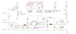
    By the way, this whole board is quite poor in components, even by Chinese standards. Only a fuse resistor protects the input, I don't see a varistor or anything else, and what's more, I don't see a second electrolytic capacitor and a filter choke either (there's only the one from the inverter).

    Here, for comparison, is a schematic of a slightly more expensive product but with a similar construction idea:
    ZigBee relay module schematic with electronic components.
    Even in Tuya products I almost always see a circuit of C0, L2, C1 (from the above schematic) and on the PCB from the topic there is not even a place for it....

    @speedy9 I wouldn't split it like that, probably it would be possible to algorithmically eliminate these incorrect on/off, worse that probably the algorithm was made for another device, then someone changed something in hardware, and now the algorithm works badly
    Helpful post? Buy me a coffee.
  • ADVERTISEMENT
  • #11 20905075
    speedy9
    Helpful for users
    p.kaczmarek2 wrote:
    I wouldn't split it like that, it would probably be possible to algorithmically eliminate these incorrect on/off switches, worse that probably the algorithm was made for another device, then someone changed something in hardware, and now the algorithm malfunctions
    Well, I don't know. These switches are rare and completely random in my opinion. It is difficult to talk about the influence of the algorithm here. On the other hand, an entry in the device log appears about the change of state.
  • ADVERTISEMENT
  • #12 20905638
    gemiel
    Level 25  
    pavlenkoblok wrote:
    To fix this, solder elements C6 0.1 mF and R1 10 kOhm in the place indicated in the photo.


    0.1 mF or maybe 0.1 uF ?
  • #13 20905651
    pavlenkoblok
    Level 2  
    >>20904846
    by supported commands - can read flash
    Screenshot of Windows PowerShell showing help for the blFlash program.
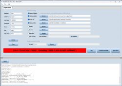
    I couldn't flash it using BLDevCube.exe, it throws an error and I couldn't do anything about it.
    Screenshot of Bouffalo Lab Dev Cube program displaying a flashing error.
    >>20904939
    Yes, on aliexpress everyone also complains about random switching and installing these elements eliminates these shortcomings.
    P.S. What unexpected activity in the topic I created! I even thought that this was not my topic :)

    Added after 10 [minutes]:

    >>20905059
    This is really a very cheap module, I bought it for $2. I'm just interested in understanding different platforms.
  • #14 20913044
    Epinet
    Level 1  
    >>20904492
    this modification is not necessary by replacing the bl602 module with an esp 02s and installing tasmota.
    I tested it and it works great
  • #15 20913301
    Adinfo
    Level 12  
    Just today I came across this thread (after last week's reprogramming of such a switch as in the thread) I took to testing with the swapped firmware on OBK.

    Unfortunately, I did not get a response to shorting contacts S1 and S2. I changed the settings in the configuration to do so, but to no avail (I thought there was something corrupted). Unfortunately, I did not check the operation of contacts S1 and S2 beforehand - before reprogramming the circuit.

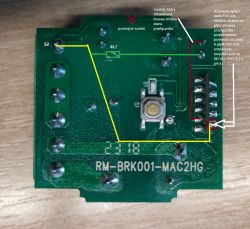
    I found out that something is wrong on the way from the connector with pin S2 and pad R in the SM-028 board. I removed excess tin from the pad marked R, which caused the disconnection of this path from the board with BL602. I found the thread https://www.elektroda.pl/rtvforum/topic3945435.html helpful. Thanks to this, GPIO_3 - pin 4 (R) and, in addition, for testing, also GPIO_2 - pin 3 (W) - both signals began to work correctly - the circuit responded to shorting with GND. I made a bridge between the pads of the R board and the via at S2 (as a precaution I inserted an additional pull up 4k7) and cut the path so that there were no elements on the way that caused the above-mentioned problem - in the circuit from the main PCB. After this operation, the circuit responds correctly to the shorting of S1 and S2.

    However, there were repeated random changes of state (transient) which caused frequent clicking and switching of the contactor (even a dozen times in a minute) - inserting a pull up resistor did not improve anything. Only the creation of a bridge between GND as in the first post of this thread solved the problem with the random change of state of the switch.

    I did not detect a short circuit, the resistance of the path on this section close to zero - full transition (not counting the leads from the meter). As for the components at the top of the board - resistor and capacitor - in my case they are factory-installed such as in the photos in the thread - but their presence does not improve the stability of the circuit at least at the time I tested, only the bridge I wrote about to GND stabilized the operation of the circuit.

    Drawing/view photo.
    Printed circuit board with marked connections, track cut, and pull-up resistor. .
  • #16 20913377
    p.kaczmarek2
    Moderator Smart Home
    @Adinfo are you using the ToggleChannelOnToggle role here? Maybe it is indeed time to separate it into three versions (versions with pull up, with pull down and without pulls) and let users choose as required. Perhaps one of these versions would do better in the original configuration of this PCB.

    But in general it's hard for me to say more, I have such modules on BK7231 alone and on them nothing switches on its own (and I know, because I even have a night light on such and somehow it doesn't turn on by itself, exactly from this topic https://www.elektroda.pl/rtvforum/topic3895572.html )
    Helpful post? Buy me a coffee.
  • #17 20913404
    Adinfo
    Level 12  
    p.kaczmarek2 wrote:
    @Adinfo are you using the ToggleChannelOnToggle role here? Maybe it is indeed time to separate it into three versions...
    Yes, I am using ToggleChannelOnToggle - in this case the problem occurred, when I changed for testing, for example, to Btn then the problem with changing the state was not observed. As for the idea with versions of ToggleChannelOnToggle is great, by the way, this topic came up today during a conversation with a friend who has seen the behavior of this switch - he just happens to have experience with ESP and there he is sometimes resorted to pull up from the level of software and internal capabilities of a particular circuit. I will try to do more tests because I have 7 more similar switches to the one in the thread (different PCB versions, but most on BK7231N and one under ZigBee). The plan is to use some staircase solutions with two mechanical switches and the others under single switches wired to S1 and S2.
  • #18 21012867
    dhanushkadx
    Level 5  
    I also have BK7231N chip and its also chnage the state of S1 so it makes the relay on and off randomly. I removed the on board buttons but the issue is exist. I ll try to add a pull out resistor.
  • #19 21013733
    dhanushkadx
    Level 5  
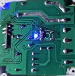
    Circuit board with a blue LED and visible traces and solder joints.


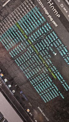
    I made this external pulled up with 4.7k with 104 cap for low pass filter. It works 100%. Pcb down side button removed. My casing has no hole for downside button. BButton existence is not relevant to this problem . I think software pull up dosent seems to be worked. Laptop screen displaying logs and configuration for an electronic project.
  • #20 21463529
    luudi1
    Level 9  
    Adinfo wrote:
    only the bridge I wrote about to GND stabilised the circuit operation.
    .

    Printed circuit board with electronic components, including a jumper and a button. .
    Gentlemen, explain to me what gives this bridge that the circuit does not trigger itself?

Topic summary

The BL602L20-based SM-028_V1.3 relay modules exhibit random relay switching issues, often turning on and off unpredictably. A hardware fix involves soldering a 0.1 µF capacitor (C6) and a 10 kΩ resistor (R1) to stabilize the relay operation. The module can be unsoldered and flashed via UART using the blflash tool with the command line interface, as BLDevCube.exe may fail. Firmware influences relay behavior through GPIO pull-up/down configurations and debouncing algorithms, but hardware modifications are crucial for reliability. Some users report that replacing the BL602 module with an ESP-02S running Tasmota firmware eliminates the problem entirely. Additional hardware improvements include adding external pull-up resistors (e.g., 4.7 kΩ) and low-pass filtering capacitors to input lines, which have proven effective in preventing false triggers. The SM-028_V1.3 board is minimalistic, lacking common protective components like varistors, additional electrolytic capacitors, or filter chokes, which may contribute to instability. Software roles such as ToggleChannelOnToggle may require variants with configurable pull-up/down settings to better match hardware. Some users have identified PCB trace issues affecting input signals (e.g., between S2 and pad R), which when corrected, improve switch responsiveness. Overall, a combination of hardware component additions, firmware adjustments, and possibly module replacement is recommended to resolve random relay switching on these BL602-based IoT devices.
Summary generated by the language model.
ADVERTISEMENT