logo elektroda
logo elektroda
X
logo elektroda

[BK7231N] [CB3S] SZKOSTON Door / Window Sensor - AAA battery - no TuyaMCU

divadiow 3393 26
ADVERTISEMENT
  • #1 20904497
    divadiow
    Level 34  
    Nothing terribly exciting about this little device. I see a few variants around but maybe not this one with CB3S module.

    CB3S Datasheet
    AliExpress product page

    I used this image to confirm I was reading the datasheet correctly. I know the pins are labelled but I wasn't sure if the GND label was to the bottom pin or the side.
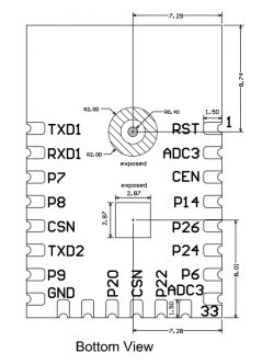
    Diagram of module pins with labels TXD1, RXD1, P7, P8, CSN, P9, GND, RST, ADC3, CEN, P14, P26, P24, P20, P22, bottom view.
    Initially I connected only the TX2 to RX on my FTDI serial adaptor as well as GND and 3.3V to get the uart boot log, which I attach. I did not power the unit with two AAA batteries, but instead used my external 3.3v power source, which is a basic MB102 PSU board attached to a small breadboard. This came as part of a cheap Amazon kit.. Some of the resistors are also 10Kohms, so useful for some flashing scenarios.
    ELEGOO electronic kit with various components on a white background.

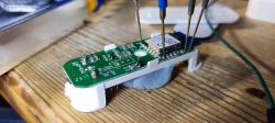
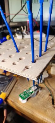
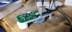
    My USB-serial adaptor/pogo probe pins/jumper wires, helping hands, are all cheapies from AliExpress. The plywood BDM platform with the holes is homemade.
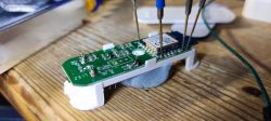
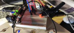
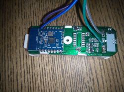
    Prototype board with CB3S module on a wooden table Breadboard with electronic components and wires. DIY test platform with a PCB and probes.

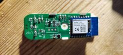
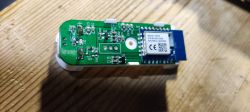
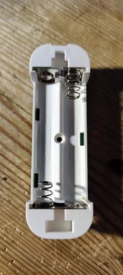
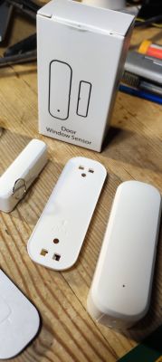
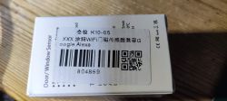
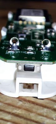
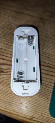
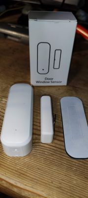
    Onto the product pictures:
    CB3S module on a green PCB with electronic components Electronic board with a CB3S module mounted on a wooden table. Battery compartment of an electronic device with visible spring contacts. Door/window sensor with packaging and casing on a wooden surface Door/window sensor packaging with informational sticker Close-up of a PCB with attached electronic components. CB3S module on a circuit board with connected test wires. View of the inside of a plastic casing with slots for AAA batteries. SZKOSTON door/window sensor set next to packaging.

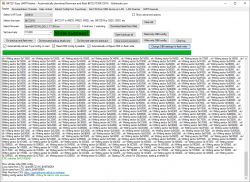
    As always I flashed with the BK7231 Easy UART Flasher, connecting RX1, TX1, GND to my breadboard/USB-serial adaptor. 3.3v provided by the MB102, not the USB-serial adaptor.

    Screenshot of BK7231 Easy UART Flasher software with a successful write message.

    I took a backup before, attached, and had the flasher write the config it found, which was

    
    Device configuration, as extracted from Tuya: 
    - Button (channel 0) on P24
    - Status LED on P26
    - PIR sensor on P8
    - Battery Relay on P14
    - Battery Max Voltage: 3000
    - Battery Min Voltage: 2200
    - Battery ADC on P23
    Device seems to use Battery Driver. See more details here: https://www.elektroda.com/rtvforum/topic3959103.html
    Device seems to be using CB3S module, which is using BK7231N.
    And the Tuya section starts, as usual, at 2023424


    {
    	"bt_pin":"24",
    	"status_led_pin":"26",
    	"rstcnt":"3",
    	"basic_pin_pin":"8",
    	"module":"CB3S",
    	"jv":"1.0.4",
    	"bt_lv":"0",
    	"net_t":"180",
    	"samp_type":"1",
    	"basic_st":"1",
    	"basic_pin_lv":"1",
    	"samp_sw_pin":"14",
    	"max_V":"3000",
    	"min_V":"2200",
    	"samp_sw_lv":"1",
    	"status_led_lv":"1",
    	"samp_pin":"23",
    	"crc":"69",
    	"}/dL(TAgw_di{abi":"0",
    	"id":"null",
    	"swv":"1.0.10",
    	"bv":"40.00",
    	"pv":"2.2",
    	"lpv":"3.3",
    	"pk":"keyhhtuxrsp7ueap",
    	"firmk":"keyhhtuxrsp7ueap",
    	"cadv":"1.0.3",
    	"cdv":"1.0.0",
    	"dev_swv":"1.0.10",
    	"s_id":"null",
    	"dtp":"0",
    	"sync":"0",
    	"attr_num":"0",
    	"mst_tp_0":"0",
    	"mst_ver_0":"null",
    	"mst_tp_1":"0",
    	"mst_ver_1":"null",
    	"mst_tp_2":"0",
    	"mst_ver_2":"null",
    	"mst_tp_3":"0",
    	"mst_ver_3":"null }{nc_tp",
    	"ssid":"null",
    	"passwd":"null",
    	"md":"0",
    	"random":"0",
    	"wfb64":"1",
    	"stat":"0",
    	"token":"null",
    	"region":"null",
    	"reg_key":"null",
    	"dns_prio":"0 } )TAgw_wsm{nc_tp",
    	"psk_key":"VuIZdIyskUqfSGOasmRncjY87xINsZybwByUL",
    	"auth_key":"SgFGqkwpEGe3BRUGnFExRzbdIy3wDbsk",
    	"ap_ssid":"SmartLife",
    	"ap_passwd":"null",
    	"country_code":"null",
    	"bt_mac":"null",
    	"bt_hid":"null",
    	"prod_test":"false",
    	"fac_pin":"7iag0uooneravbjb }sK(SAgw_ainull",
    	"lckey":"null",
    	"h_url":"null",
    	"h_ip":"null",
    	"hs_url":"null",
    	"hs_ip":"null",
    	"hs_psk":"null",
    	"hs_psk_ip":"null",
    	"mqs_url":"null",
    	"mqs_{uuid":"df72a05a5860a1f0",
    	"mq_url":"null",
    	"mq_ip":"null",
    	"ai_sp":"null",
    	"ai_sp_ip":"null",
    	"mq_psk":"null",
    	"mq_psk_ip":"null",
    	"time_z":"null",
    	"s_time_z":"null",
    	"wx_app_id":"null",
    	"wx_uuid":"null",
    	"dy_tls_m":"0",
    	"cloud_cap":"0",
    	"psk21_key":"null } )TAgw_wsm{nc_tp",
    	"ap_s{bt_pin":"24"
    }


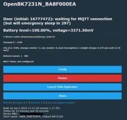
    I notice it detected P8 as a PIR sensor, so set "dInput" instead of "DoorSnsrWSleep", which is what I gather should be set for this type of device. I have use for this device yet, and don't even have a working MQTT/Home Assistant setup, so do not yet understand how the presence of the magnet (when door closed) translates into the value in the web gui or what means for HA.

    Device configuration panel with BK7231N module

    OBK Template
    Code: JSON
    Log in, to see the code


    Questions:

    Why is dInput/PIR detected? (what is "basic_pin_pin"? is it an undetectable generic input?)
    Why does the sleep timer count down from 300s but quickly reset itself back to 300s on battery and external 3.3v?
    Should there be another deep sleep setting I should enable?

    Many thanks
  • ADVERTISEMENT
  • Helpful post
    #2 20911982
    p.kaczmarek2
    Moderator Smart Home
    I think that basic_pin_pin was found first in PIR sensor and we were not aware that the same syntax is used also in door sensors, that's why template extractor detects it as PIR.

    Regarding 300 seconds countdown - well, the driver is created with assumption that it's supposed to work with MQTT. I don't think this sensor can be much useful without that. I think you'd need to setup MQTT first for it to work correctly. Still, if you want to try using it without MQTT (I don't know, maybe script device to send HTTP GET on trigger), I can also try to figure out something for you. It's just it's not the expected use case.

    Keep in mind that you can as well ignore the door sensor driver and write your own custom behaviour in the script.

    Using this device without any server like Home Assistant is especially tricky because it is in deep sleep most of the time so you can't just query it to see if the doors are open. The WiFi module does not run when in deep sleep, so it will appear offline for you. This is why we usually use such devices along with Home Assistant.
    Helpful post? Buy me a coffee.
  • #3 20961348
    bieskholodov
    Level 1  

    >>20904497
    Why does the sleep timer count down from 300s but quickly reset itself back to 300s on battery and external 3.3v?

    "14": "BAT_Relay;0",

    ok "14": "BAT_Relay;1",
  • #4 20961796
    divadiow
    Level 34  
    bieskholodov wrote:
    ok "14": "BAT_Relay;1",


    14 should be bat_relay:1?

    I've not setup MQTT/HASS for this device yet to test
  • #5 21122816
    Nordlicht77
    Level 9  
    Hi,
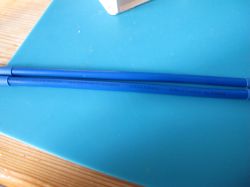
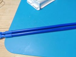
    what long blue sample pin holders are these?

    Blue pin holders attached to a wooden board with holes.
  • ADVERTISEMENT
  • #8 21122867
    divadiow
    Level 34  
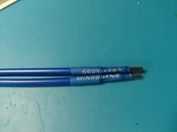
    looks pretty much the same. the ones Ali sent didn't have black ends though.

    Two blue wires on a blue surface, marked as 450/750V.
    Close-up of blue electrical wires on a light blue surface. Two blue electrical wires with black ends and markings 660V/125°C MINGGUANG.

    Added after 1 [minutes]:

    I must admit I use them less and less now in favour of soldering
  • #10 21122995
    divadiow
    Level 34  
    not especially. I did spend hours sometimes where soldering would have been much more reliable
  • #11 21158464
    Jacekmiel1
    Level 7  
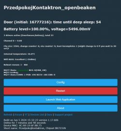
    He digs it out. I bought this module and managed to upload OBK to it. I have configured WiFi and MQTT. My home page looks like this:
    Screenshot of a Tuya device interface displaying battery level, temperature, and WiFi status data.

    The batteries are new, so the indication is probably correct. Unfortunately, I have a problem with the opening sensor. In home assistant I see it like this:

    User interface of door contact monitoring system.
    Even though the magnetic probe is touched to its side, the sensor still informs about its opening.
    What is also strange for me is the fact that every time the module communicates with my mqtt server, a shutdown is also sent.

    Please help me find the problem.

    This is my configuration:
    {
    "vendor": "Tuya",
    "bDetailed": "0",
    "name": "Full Device Name Here",
    "model": "enter short model name here",
    "chip": "BK7231N",
    "board": "TODO",
    "flags": "1024",
    "keywords": [
    "TODO",
    "TODO",
    "TODO"
    ],
    "pins": {
    "8": "DoorSnsrWSleep;0",
    "14": "BAT_Relay;0",
    "23": "BAT_ADC;0",
    "24": "Btn;0",
    "26": "WifiLED_n;0"
    },
    "command": "",
    "image": "https://obrazki.elektroda.pl/YOUR_IMAGE.jpg",
    "wiki": "https://www.elektroda.com/rtvforum/topic_YOUR_TOPIC.html"
    }
  • #12 21158501
    p.kaczmarek2
    Moderator Smart Home
    On Elektroda.com, we speak English. elektroda.pl is for polish posts.

    I see you've set DoorSnsrWSleep IO role. Have you tried to use DoorSnsrWSleep_nPup or DoorSnsrWSleep_pullDown, whatever it was called? There are at least 3 similiar roles to choose from.
    Helpful post? Buy me a coffee.
  • #13 21158505
    Jacekmiel1
    Level 7  
    >>21158501Sorry for my mistake. I translated my post to English.
  • #14 21158520
    p.kaczmarek2
    Moderator Smart Home
    No problem, it's just important because foreigners are reading these posts and they don't know Polish.

    So, did you try the other roles? Find the one that can read both states (closed and open) correctly.
    Helpful post? Buy me a coffee.
  • #15 21158623
    Jacekmiel1
    Level 7  
    >>21158520 I tried options: DoorSnsWSleep_nPup, DoorSnsWSleep_pd and classic DoorSnsWSleep work the same. I am receiving short open/close message
  • ADVERTISEMENT
  • #16 21158669
    p.kaczmarek2
    Moderator Smart Home
    Maybe issue is somewhere else and I misunderstood you.

    Maybe you need to set a startup value to -1 for your channel which you are using for door state, so it does not start always as 0 on reboot?
    Helpful post? Buy me a coffee.
  • #17 21158895
    insmod
    Level 25  
    Try to configure separate channels for doorsensor, btn and bat_relay. AFAIK, when battery driver measures voltage, it briefly toggles the configured channel, and you have it configured on the same channel, as doorsensor.
  • #18 21375427
    minusync
    Level 9  
    divadiow wrote:
    My USB-serial adaptor/pogo probe pins/jumper wires, helping hands, are all cheapies from AliExpress. The plywood BDM platform with the holes is homemade.


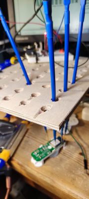
    How did you actually wire the sensor? I can't see explanation about that. I can guess that 3.3 and gnd are directly connected to chip. So more or less standard setup?
    I have tried directly to chip and also powering whole board but cannot read it.
    I have similar board but not exactly, maybe it needs separate thread.

    Close-up of a circuit board with attached wires.
  • #19 21375826
    divadiow
    Level 34  
    direct connections to module pads using pogo pins
    Electronic module with connected pogo pins on a desk

    Module RX -> USB-TTL TX
    Module TX -> USB-TTL RX
    Module 3.3V -> Ext PSU 3.3V
    Modul GND -> Common USB-TTL GND/Ext PSU GND
  • ADVERTISEMENT
  • #20 21376817
    minusync
    Level 9  
    divadiow wrote:
    direct connections to module pads using pogo pins


    One more question - when you do remember.
    On old days there were always all pads from module soldered on board. Nowadays I see more and more that sometimes only half or so are soldered. I guess that the rest are not needed.
    On my board CB3's GND was not soldered to the board. At least not visually as those clearly soldered ones. This really confuses me and I suspect that this is somehow related to the fact that I am not able to read or write to it.
    On your CB3's, was GND soldered from the factory or not?
    thanks
  • #21 21376991
    divadiow
    Level 34  
    minusync wrote:
    On your CB3's, was GND soldered from the factory or not?


    yes. I notice the amount of solder can vary to the point where it looks like there isn't any. The module wouldn't work without the ground soldered.

    Added after 4 [minutes]:

    have you checked your soldering for any whiskers between pads? continuity between adjacent pads? is there continuity between the gold leaf of unsoldered pad area through to the end of your soldered wires? how long are your wires?
  • #22 21377825
    minusync
    Level 9  
    divadiow wrote:
    I notice the amount of solder can vary to the point where it looks like there isn't any. The module wouldn't work without the ground soldered.


    That was my first thought but it isn't necessarily true.
    All parts of board use GND
    There are several ways to get GND (basically u can imagine things as serial and probably get GND also thru other pins)

    I am 99% sure that on my board dedicated GND pin is not soldered on. However I was able to flash it when I soldered wire on top part of GND pin.
    Basically when there is not factory made connection between CB3S pin and board you need to make sure that you make contact with CB3S GND not board below it. After that everything went well.

    If somebody knows answer: I noticed that now with new OB device there is always diagnostic part of device that never works. Is this new OB thing or related to HA? Should it actually work?
  • #23 21449716
    taggbricka
    Level 6  
    I have some of these door switches.
    I have a lab development environment with a WiFi network.
    I have another building with its own WiFi network.

    So I thought I set SSID to lab network and SSID2 to the deployment network.
    The device will not connect to SSID2 when SSID is not up, it blinks for a very long time without connecting.
    For debugging I swapped SSID and SSID2, but I always get only the network defined by SSID
    There is no AP showing up either, it just blinks.

    Is there a setting that I have missed?
  • #24 21596593
    styb113
    Level 4  
    >>20904497
    I flashed this device with OpenBeken long ago. I was wondering if it would be possible to flash this device back to the Tuya software? I don't have my firmware dump anymore. Is it possible to use your firmware dump bin? Or are these device specific? This is the first time I want to switch back.
  • #25 21596661
    divadiow
    Level 34  
    Assuming your device is identical, it would probably work. I always thought the factory pin, if specified, was unique to each device but that might be an incorrect assumption. You could flash it, pair it, then I could pair it too to see my registration steals it away from your account or something.
  • #26 21596683
    insmod
    Level 25  
    >>21596661
    Backup needs to be cut to 1224kb to preserve original mac/calibration and tuya keys
  • #27 21596702
    divadiow
    Level 34  
    Good thinking. Maybe the user should take full flash backup first to preserve these areas should anything go awry with the procedure?

Topic summary

The discussion centers on the SZKOSTON Door/Window Sensor featuring the BK7231N chip and CB3S module, powered by AAA batteries without TuyaMCU. The original poster verified pinouts using the CB3S datasheet and images, powering the device via an external 3.3V supply and interfacing through UART with an FTDI serial adapter. Challenges include interpreting the sensor's sleep timer behavior, MQTT integration necessity, and configuring correct IO roles (e.g., DoorSnsrWSleep variants) for accurate door state detection in Home Assistant. Users highlight the difficulty of using the sensor without MQTT due to deep sleep mode disabling WiFi, causing offline status. Wiring details emphasize direct connections to module pads with pogo pins, noting variability in factory soldering quality, especially for the GND pin, which can affect flashing and communication. Suggestions include separating channels for door sensor and battery relay to avoid signal conflicts. Additional hardware accessories like pogo pins from AliExpress and Amazon are discussed, with reliability concerns favoring soldering over probe contacts. Network configuration issues arise when setting dual SSIDs, with the device failing to connect to the secondary SSID if the primary is unavailable. Overall, the thread provides practical insights into hardware interfacing, firmware flashing, MQTT setup, and troubleshooting for this specific door/window sensor module.
Summary generated by the language model.
ADVERTISEMENT