logo elektroda
logo elektroda
X
logo elektroda

Flashing BK7231N on CBL C9S Mini Curtain Module - Unable to Enter Flash Mode

dawsonlebrown 2052 12
ADVERTISEMENT
  • #1 20907548
    dawsonlebrown
    Level 3  

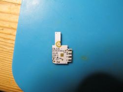
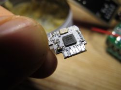
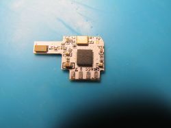
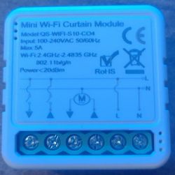
    Mini Wi-Fi Curtain Module with technical label Hi, I'm trying to flash a "Mini Wi-Fi Curtain Module" with OpenBeken, but can't get it to enter flash mode. The device has a BK7231N on a module labeled "CBL C9S" - it looks similar to, but not identical to the CBL C9 module.

    I am able to get debug info from the TX02 port, but I have not been able to convince it to go into flashing mode on the TX01/RX01 port, and I'm hoping someone here will be able to point me in the right direction.

    With 3.3v from an external power supplied to the pad marked VCC, and GND connected to the pad marked GND (also works connected to various other GND connected points on the board) I am able to power up the device.

    With BK7231Flasher.exe, I start the backup & flash process with the latest firmware, then try to get the chip into flash mode - tried shorting the CEN pad to ground, disconnecting the 3v3 and reconnecting it, disconnecting the GND and reconnecting it - but I keep getting "Getting bus failed. will try again"

    Using Arduino IDE, I am able to get a debug log from TX02, and I am also able to get a log from TX01 IF I reboot the module with the CSN pad pulled to GND, I tried this configuration in BK7231Flasher.exe to see if it would be in flash mode, but no luck.

    I was wondering if the device was using one of the UART pins, causing communication problems, so desoldered and removed the module, but still get the same results.😒
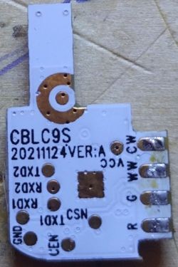
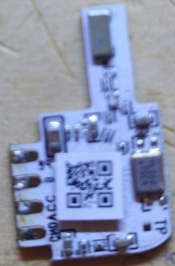
    CBL C9S module for mini Wi-Fi with visible pads VCC, GND, TXD2, RXD2, RX01, TX01, and CSN. Mini Wi-Fi module with BK7231N chip on a board labeled CBL C9S.
    Do you have a problem with Arduino? Ask question. Visit our forum Arduino.
  • ADVERTISEMENT
  • #2 20907667
    p.kaczmarek2
    Moderator Smart Home
    Welcome to forum. So, how does your flashing circuit look like? Even long wires may interfere with flashing.
    Have you tried swapping RX with TX?
    Helpful post? Buy me a coffee.
  • ADVERTISEMENT
  • #3 20909106
    dawsonlebrown
    Level 3  

    Thanks for the welcome and the quick reply!

    Yes, I've tried swapping TX/RX, but considering that when the pin marked TX01 is connected to RX on my UART connector, I am able to get log dumps, I'm pretty sure that I've identified the correct pairing.

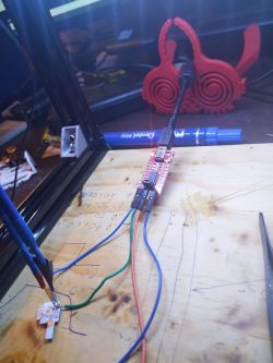
    Here's a photo of my latest flashing setup. Considering your suggestion of the length of wires, I soldered some very short wires (about 8cm long) for the RX/TX pair - I don't imagine the length of wires is a factor for the 3.3/GND wires, so to avoid unnecessary soldering, I've left them as is with the pogo pins. Even with these shorter wires, I'm getting the same results as with the longer wires and pogo sticks.
    Microcontroller flashing setup with short wires.
    Damn, just after taking the photo, the wire soldered to the RX pad tore off the module, taking the pad with it😖 so I guess I won't be able to test any other suggestions 😒

    I've successfully flashed about 10 devices with this setup. For the first few, I soldered longer (about 15cm) wires to the boards, and for the latest, with pogo pins and so, no soldering. This CBL C9S is the second module I've been unable to get into flash mode, the other being a CB2S in a "Mini smart switch".
  • #4 20909580
    p.kaczmarek2
    Moderator Smart Home
    Is there any good 3.3V LDO on the UART to USB converter you are using? I saw you mentioned you power it in a better way, but I can't see that. As I said just few minutes ago in another thread, you need to have a good 3.3V power supply for flashing, otherwise it will not work. It has to be something like AMS1117-3.3V, you can't just use 3.3V pin from cheap USB to UART converter.

    Have you watched any of our BK7231 flashing tutorials on Youtube?
    https://www.youtube.com/@elektrodacom
    We just have a lot of them.
    This playlist (look for BK7231):
    https://www.youtube.com/watch?v=L6d42IMGhHw&list=PLzbXEc2ebpH0CZDbczAXT94BuSGrd_GoM

    Or if you are powering it correctly, then maybe you forgot to connect the common ground? Power supply GND should connect to USB to UART converter GND.

    You can also try using the USB to UART converter that I am using. I had few reports saying that using different USB to UART converter helped.

    How bad is the pad damage? Is there still a trace?
    Helpful post? Buy me a coffee.
  • ADVERTISEMENT
  • #5 20909627
    dawsonlebrown
    Level 3  

    It is a cheap USB UART converter, but I have successfully flashed all but one of the devices which I've successfully flashed with the 3V3/GND from the converter. For the one device which it didn't supply enough power, I used my bench power supply (2A max) - voltage set to 3.3, and, yes I tied the grounds together.

    I tried both doing just with the converter's power, with just the power supply - and with both together in parallel.

    The pad damage is pretty bad - even a bit of the trace leading up to the pad is gone. I could try putting the pogo stick directly on pin 26 of the BK7231N on the module, but it would be difficult to be sure that I have actually hit the right pin, if any at all.

    Yep, I've watched a bunch of your videos, but haven't found anything in your vids or elsewhere online for this specific module. Its not even listed it its EXACT configuration on Tuya developer portal As I mentioned in my first post, it is similar to, but not identical to the CBL C9 - mine has an S at the end and the pad positions are different to those shown on the website. I wonder if Tuya have modified the module somehow to protect it from being reflashed?
  • Helpful post
    #6 21288183
    divadiow
    Level 34  
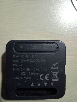
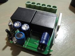
    I have pretty much the same device but in black and the model is marked as QS-WIFI-CP03 - I didn't know CBLC9S modules were a thing

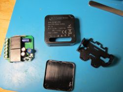
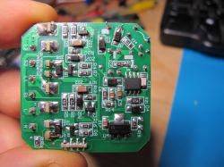
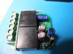
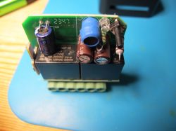
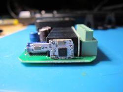
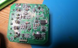
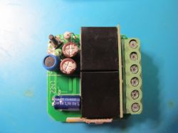
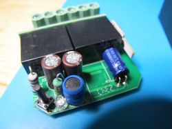
    Dismantled Wi-Fi Curtain Module QS-WIFI-CP03.

    Image of an electronic module with components on a green printed circuit board. Electronic module with capacitors and screw terminals on a blue background. Electronic module with various components, including capacitors and a relay. Close-up of an electronic module on a green printed circuit board. Image of a printed circuit board with electronic components. Electronic module with soldered components and screw terminals. Electronic circuit with capacitors and relays on a green PCB.

    here is the boot log from TXD2
    Code: Text
    Log in, to see the code


    Attached is unpaired factory firmware - V2.0.1 - Cloudcutter profiles - https://github.com/search?q=repo%3Atuya-cloud...cutter.github.io%20uoa3mayicscacseb&type=code

    config in binary after pairing to Tuya app
    Code: JSON
    Log in, to see the code


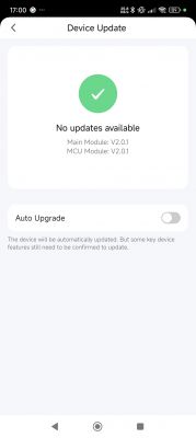
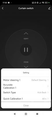
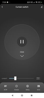
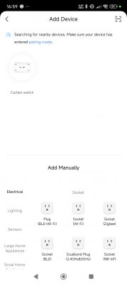
    Device update screen showing no updates available. Module versions are V2.0.1. App interface for controlling a curtain switch. Curtain control app with a pause button, a curtain slider, and bottom screen options. App screen for adding a device, showing a detected curtain switch labeled Curtain switch and an option to manually add various types of sockets.
  • ADVERTISEMENT
  • #8 21351411
    GAAD
    Level 17  
    Hi
    I have something similar: WiFi Curtain Module Model: QS-WiFi-CP03.
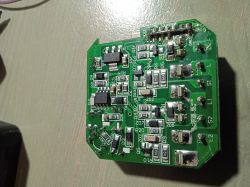
    Back of the QS-WiFi-CP03 WiFi Curtain Module with specifications Photo of an electronic module with capacitors and relays on a green circuit board.

    Another module inside:

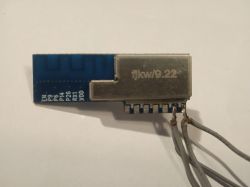
    Electronic module with fjkw/9.22 marking and wires

    I flashed it
    Built on Dec 15 2024 08:09:38 version 1.17.800
    Short name: Roleta_6, Chipset BK7231N
    I didn't make a backup because there was a CRC error. Baud rate: 921600

    My configuration:
    
    {
      "vendor": "Tuya",
      "bDetailed": "0",
      "name": "Full Device Name Here",
      "model": "enter short model name here",
      "chip": "BK7231N",
      "board": "TODO",
      "flags": "1156",
      "keywords": [
        "TODO",
        "TODO",
        "TODO"
      ],
      "pins": {
        "6": "Btn;1",
        "8": "Btn;2",
        "9": "Rel;1",
        "23": "Btn;0",
        "24": "Rel;2"
      },
      "command": "",
      "image": "https://obrazki.elektroda.pl/YOUR_IMAGE.jpg",
      "wiki": "https://www.elektroda.com/rtvforum/topic_YOUR_TOPIC.html"
    }


    It works fine with the configuration from @rodionzhitomirsky in this thread:
    https://www.elektroda.com/rtvforum/topic4015497.html#20910126

    Thanks for your work
    Wojtek
  • #9 21351571
    divadiow
    Level 34  
    That's an interesting module.

    It's a shame about the backup CRC :(

    Do you have a partial file still or was nothing saved at all?
  • #12 21352709
    GAAD
    Level 17  
    I will disassemble and program one more unit, if necessary I will take a better photo.
    Close-up of a green circuit board with various electronic components.

Topic summary

The discussion revolves around difficulties in flashing a Mini Wi-Fi Curtain Module with a BK7231N chip, specifically the CBL C9S model. The user is unable to enter flash mode despite successfully obtaining debug information from the TX02 port. Various troubleshooting steps have been attempted, including swapping RX and TX connections, using short wires, and ensuring proper power supply connections. The user has experienced pad damage on the module, complicating further attempts. Suggestions from other forum members include ensuring a reliable 3.3V power supply, checking ground connections, and considering alternative USB to UART converters. A similar device, marked QS-WIFI-CP03, was also mentioned, indicating potential variations in the module design.
Summary generated by the language model.
ADVERTISEMENT