logo elektroda
logo elektroda
X
logo elektroda

WIP [CBLC9 / BK7231N] Mini WIFI Curtain Module QS-WIFI-S10-C4

vincenzoernst1 4566 25
ADVERTISEMENT
  • #1 21049246
    vincenzoernst1
    Level 8  
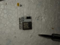
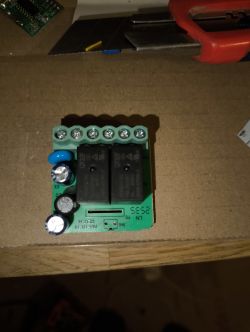
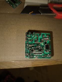
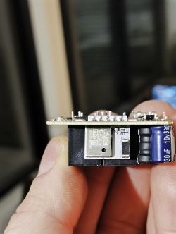
    This Curtain Module is similar to RTX WCM1MR which also uses the CBLC9/BK7231N


    Board ID: QL-0887
    Rev. A
    2024.01.23


    PIN CBLC9 Board
    P6ext. switch
    P7relay down
    P8LED
    P9relay up
    P24internal push button
    P26ext. switch
    GNDGND
    VCC3.3V


    I flashed OpenBK on Linux cli via python. The bus was not detected at 1st but as soon as i disconnected the board from 3.3V, started to flash and reconnected the board to 3.3V, the bus was detected and the flashing/backup started.

    i dont use the mechanical button right now.

    Current config:
    {
      "vendor": "Tuya",
      "bDetailed": "0",
      "name": "QS-WIFI-S10-C04",
      "model": "Mini WiFi Curtain Module",
      "chip": "BK7231N",
      "board": "CBLC9",
      "flags": "1024",
      "keywords": [
       "shutter",
        "blind",
        "roller",
        "curtain",
        "awning",
       "sunblind",
       "marquee",
       "slat",
      ],
      "pins": {
        "6": "Btn;1",
        "7": "Rel;2",
        "8": "WifiLED_n;0",
        "9": "Rel;1",
        "24": "Btnl;32",
        "26": "Btn;2"
      },
      "command": "PowerSave 1",
      "image": "https://obrazki.elektroda.pl/1978468300_1713373135.jpg",
      "wiki": "https://www.elektroda.com/rtvforum/viewtopic.php?p=21049246"
    }


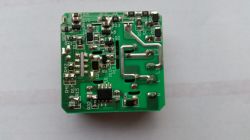
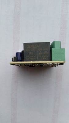
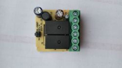
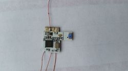
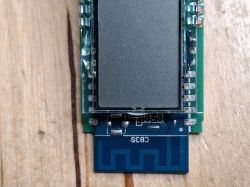
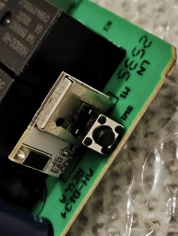
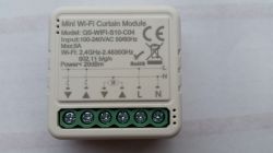
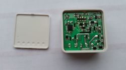
    Mini Wi-Fi Curtain Module QS-WIFI-S10-C04 with technical specifications printed on the casing and visible screw terminals. Green electronic module circuit board with open casing.Close-up of a printed circuit board with electronic components. Electronic module with QLRELAY relay and green terminal. Electronic board module labeled QL-0887 Rev. A.Curtain module circuit board with connected wires. Image of a curtain module with attached wires.

    Attached the orig firmware backup. I used the python cli tool. 1st backup with "-r", 2nd with "-r -s 0x0"
  • ADVERTISEMENT
  • #2 21049729
    p.kaczmarek2
    Moderator Smart Home
    Hey, the backup should be full 2MB, not just 1.1MB. Full 2MB will allow you to do the config extraction. We're usually using this tool:
    https://github.com/openshwprojects/BK7231GUIFlashTool
    However, you can also extract config after flashing:


    Helpful post? Buy me a coffee.
  • ADVERTISEMENT
  • #3 21050156
    vincenzoernst1
    Level 8  

    next: i have to figure out how to set "shutter mode".
  • #4 21124638
    mic_jan
    Level 11  
    Hey, and can these QS-WIFI-S10-C04 be reflashed via https://github.com/tuya-cloudcutter/tuya-cloudcutter ?
    For the aforementioned RTX WCM1MR I found a profile, but for the right one I didn't and I'm stuck, and I didn't want to solder out the module.

    
    Selected Device Slug: tuya-generic-2ch-curtain-module
    Selected Profile: oem-bk7231n-curtain-switch-1.1.0-sdk-2.3.1-40.00
    Selected Firmware: OpenBeken-v1.17.262_bk7231n.ug.bin
    
    ================================================================================
    Place your device in AP (slow blink) mode.  This can usually be accomplished by either:
    Power cycling off/on - 3 times and wait for the device to fast-blink, then repeat 3 more times.  Some devices need 4 or 5 times on each side of the pause
    Long press the power/reset button on the device until it starts fast-blinking, then releasing, and then holding the power/reset button again until the device starts slow-blinking.
    See https://support.tuya.com/en/help/_detail/K9hut3w10nby8 for more information.
    ================================================================================
    
    Scanning for open Tuya SmartLife AP
    .........
    Found access point name: "SmartLife-2B41", trying to connect...
    Error: Connection activation failed: (53) The Wi-Fi network could not be found.
    Connected to access point.
    Waiting 1 sec to allow device to set itself up...
    Running initial exploit toolchain...
    Exploit run, saved device config too!
    output=/work/configured-devices/4RDQRMO6jvbI.deviceconfig
    Saved device config in /work/configured-devices/4RDQRMO6jvbI.deviceconfig
    
    ================================================================================
    Power cycle and place your device in AP (slow blink) mode again.  This can usually be accomplished by either:
    Power cycling off/on - 3 times and wait for the device to fast-blink, then repeat 3 more times.  Some devices need 4 or 5 times on each side of the pause
    Long press the power/reset button on the device until it starts fast-blinking, then releasing, and then holding the power/reset button again until the device starts slow-blinking.
    See https://support.tuya.com/en/help/_detail/K9hut3w10nby8 for more information.
    ================================================================================
    
    Scanning for open Tuya SmartLife AP
    .....
    Found access point name: "SmartLife-2B41", trying to connect...
    Error: Connection activation failed: (53) The Wi-Fi network could not be found.
    ...
    Found access point name: "SmartLife-2B41", trying to connect...
    Error: Connection activation failed: (53) The Wi-Fi network could not be found.
    ......
    Found access point name: "SmartLife-2B41", trying to connect...
    Error: Connection activation failed: (53) The Wi-Fi network could not be found.
    ......
    Found access point name: "SmartLife-2B41", trying to connect...
    Error: Connection activation failed: (53) The Wi-Fi network could not be found.
    Connected to access point.
    ================================================================================
    [!] The profile you selected did not result in a successful exploit.
    ================================================================================
    
    .

    Am I doing something wrong or is it just the way it is?

    Or is it possible without soldering to see what the CHIP is?
  • #5 21124664
    p.kaczmarek2
    Moderator Smart Home
    A lot of new devices are already secure. Newer batches of these models may not be susceptible to exploitation either.

    You can tell from the error message that you haven't set the AP pairing mode on the device, so there's still a chance this will work.

    But the device in question is rather easy to open, why would you want to combine?

    How many of these devices do you have, do you have anything outside of our Electrode list? I can upload a flash for you if needed, details on PW.
    Helpful post? Buy me a coffee.
  • #6 21125233
    vincenzoernst1
    Level 8  
    it should also flashable without desoldering. you have access to all pins and if the flasher delivers enough current it should be working.
  • #7 21125913
    mic_jan
    Level 11  
    It's either blocked or I'm doing something wrong.

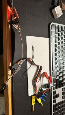
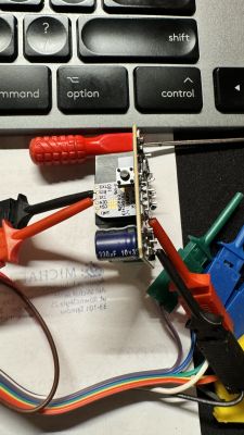
    I made an attempt to connect to the UART without soldering, but could not establish communication.

    UART cables connected to a board next to a keyboard. Soldered PCB connected to colorful wires, placed in front of a keyboard. .

    I also tried tapping the UART via minicom , but to no avail.

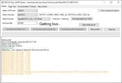
    I tried downloading the firmware via BK7231GUIFlashTool , and here I had all the time (picture borrowed, but it was getting to 100/100 and crashing)

    Screenshot of the BK7231 Easy UART Flasher program showing a firmware download attempt with error messages.
  • #8 21125926
    p.kaczmarek2
    Moderator Smart Home
    Are you performing the operations as instructed?
    https://www.youtube.com/playlist?list=PLzbXEc2ebpH0CZDbczAXT94BuSGrd_GoM
    You need to enable flashing so that the flasher tries to "get bus", and then cut the power for a while so that the flasher "catches" the chip booting up.

    Added after 46 [seconds]: .

    In addition, the connections look unacceptably long.
    Helpful post? Buy me a coffee.
  • #9 21125978
    mic_jan
    Level 11  
    I tried with unplugging the power supply, using CEN to GND and nothing :(
  • #10 21125999
    p.kaczmarek2
    Moderator Smart Home
    Are you powering this according to the tutorials, i.e. from a good 5V power supply to the 3.3V LDO input? Or are you trying from that 3.3V pin on a USB to UART converter, which has no current capacity?

    Well, and as I wrote, those wires are rather too long.
    Helpful post? Buy me a coffee.
  • #11 21126068
    mic_jan
    Level 11  
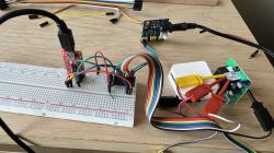
    I'm powering it 12V -> 3.3Vi I modified the connections a bit, shorter crocodiles I don't have.

    Breadboard with connected wires and electronic components. .

    I don't know if I should use any more components?
  • #12 21126071
    p.kaczmarek2
    Moderator Smart Home
    I still think the connections are too long. We have documented cases on the forum when users also had cables like yours and it didn't work, only shortening helped.

    Apart from that, try swapping the RX with the TX (as a general rule).

    When programming, proceed as follows:
    1. enable read flash in flasher
    2. let it try "getting bus"
    3. then disconnect the 3.3V from the WiFi module side
    4. connect the 3.3V from the WiFi Router (NOT from the power supply) to GND
    5. then connect the 3.3V back to the power supply...

    You can also try another USB to UART converter and try to connect 5V from USB to the AMS1117-3.3V input and use this 5V to do power off/on.
    Helpful post? Buy me a coffee.
  • #13 21142835
    mic_jan
    Level 11  
    We have managed to get the QS-WIFI-S10-C04 to flash with TUYA Cloud Cutter .

    And everything would work, but you can turn on both relays at once, which would burn up the motor, and the pairing button doesn't work like in the TUYA software, that when it's not in pairing mode, it handles the relays, that the first press turns on, the next press turns off the first relay, the next press turns on the second relay, and the next press turns off the second relay. I hope I haven't messed anything up.

    Also, the operation of the roller shutter buttons doesn't work properly, because pressing open will turn on the relay, but if I press close, it won't turn off the opening relay and it won't turn on the closing relay, it just brings both relays on.

    I used such an autoexec.bat:

    //Configurar alias  Aliases
    alias Set_Stop backlog setChannel 2 0; setChannel 1 0
    alias Set_Open backlog setChannel 1 1
    alias Set_Close backlog setChannel 2 1
    alias Start_Opening backlog stopAllScripts; startScript autoexec.bat openBlind
    alias Start_Closing backlog stopAllScripts; startScript autoexec.bat closeBlind
    alias Stop_All backlog stopAllScripts; startScript autoexec.bat stopBlind
    
    // Channel 60 segundos de trabajo
    setChannel 60 15
    
    //crear botones GUI  para el panel HTTP
    startDriver httpButtons
    
    setButtonEnabled 1 1
    setButtonLabel 1 "Open"
    setButtonCommand 1 Start_Opening
    
    setButtonEnabled 3 1
    setButtonLabel 3 "Close"
    setButtonCommand 3 Start_Closing
    
    setButtonEnabled 2 1
    setButtonLabel 2 "Stop"
    setButtonCommand 2 Stop_All
    setButtonColor 2 red
    
    // Ocultar los botones de los reles en la  GUI HTTP
    setChannelVisible 1 0
    setChannelVisible 2 0
    setChannelVisible 3 0
    
    // Cargar Event Handlers
    addEventHandler OnHold 26 Start_Closing
    addEventHandler OnHold 24 Start_Opening
    addEventHandler OnClick 11 Stop_All
    
    // Detener persiana al encender
    goto stopBlind
    return
    
    // Script abrir
    openBlind:
    Set_Stop
    delay_s 0.1
    Set_Open
    delay_s $CH60
    Set_Stop
    return
    
    // Script cerrer
    closeBlind:
    Set_Stop
    delay_s 0.1
    Set_Close
    delay_s $CH60
    Set_Stop
    return
    
    // Script detener
    stopBlind:
    Set_Stop
    return
    .

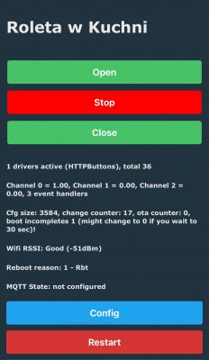
    and I got the following and it works, but only from the web panel.
    Control panel for kitchen blind with buttons Open, Stop, and Close. .

    What am I doing wrong, or how do I get a situation similar with Tasmota so that there is an Interlock?

    I haven't zipped into HomeAssistant yet so won't comment.
  • ADVERTISEMENT
  • Helpful post
    #14 21151245
    mic_jan
    Level 11  
    Update:
    I have used as input the template import:
    
    {
      "vendor": "Tuya",
      "bDetailed": "0",
      "name": "QS-WIFI-S10-C04",
      "model": "Mini WiFi Curtain Module",
      "chip": "BK7231N",
      "board": "CBLC9",
      "flags": "1024",
      "keywords": [
       "curtain",
       "blind",
       "rollers",
       "roller",
       "shutters",
       "shutter",
       "awning",
       "sunblind",
       "marquee",
       "WiFi"
      ],
    "pins": {
      "6": "Btn;1",
      "7": "Rel;2",
      "8": "WifiLED_n;0",
      "9": "Rel;1",
      "24": "Btn_Tgl_All;0",
      "26": "Btn;2"
    },
    "command": "PowerSave 1",
    "image": "https://obrazki.elektroda.pl/1978468300_1713373135.jpg",
    "wiki": "https://www.elektroda.com/rtvforum/viewtopic.php?p=21049246"
    }
    
    .

    while as logic an autoexec.bat file modelled on thread user @maxim2002 modified under my Tuya:
    
    // drivers
    startDriver httpButtons
    startDriver NTP
    ntp_timeZoneOfs 02:00
    
    // config
    powerSave 1
    setFlag 2 1 // MQTT Broadcast self state
    setFlag 6 1 // BTN Instant touch
    setFlag 27 1 // HASS discovery on IP change
    setFlag 41 0
    setButtonTimes 1 1 1
    
    // shutter cycle
    setChannel 40 42 // seconds
    
    // position (open 0 - N closed in seconds)
    setChannelType 41 ReadOnly
    setChannelLabel 41 "Position"
    setChannel 41 $CH40 // closed
    
    // relays
    setChannelType 1 toggle
    setChannelLabel 1 "Open"
    setChannel 1 0
    addChangeHandler Channel1 == 1 backlog cancelRepeatingEvent 1; cancelRepeatingEvent 2; setChannel 2 0; addRepeatingEventID $CH40 1 1 setChannel 1 0; setChannel 41 $CH41-1; addRepeatingEventID 1 -1 11 setChannel 41 $CH41-1
    addChangeHandler Channel1 == 0 cancelRepeatingEvent 11
    
    setChannelType 2 toggle
    setChannelLabel 2 "Close"
    setChannel 2 0
    addChangeHandler Channel2 == 1 backlog cancelRepeatingEvent 1; cancelRepeatingEvent 2; setChannel 1 0; addRepeatingEventID $CH40 1 2 setChannel 2 0; setChannel 41 $CH41+1; addRepeatingEventID 1 -1 22 setChannel 41 $CH41+1
    addChangeHandler Channel2 == 0 cancelRepeatingEvent 22
    
    return
    
    .

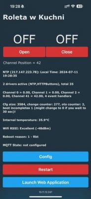
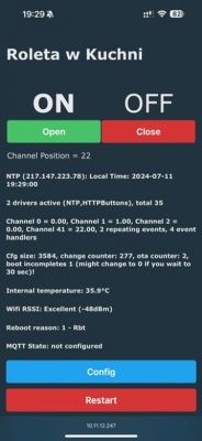
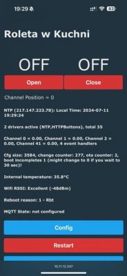
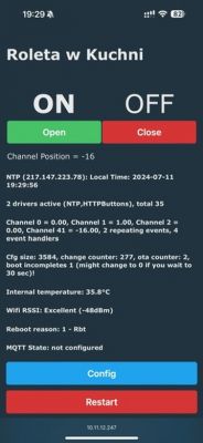
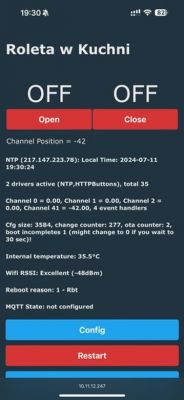
    Generally everything works correctly except the position, which when closed is 42, when opened goes to 0, but when I have closed, click OPEN and click again OPEN, the position becomes -42 and so on. The other way it is also the case that if I have a position at 0 and I give CLOSE it goes to 42, and if I CLOSE again I have 84 as in the attached screens:

    Screenshot of a curtain control application for the kitchen on a smartphone. Curtain control screen in the kitchen with Open and Close buttons. App screen for managing a kitchen blind with Open and Close buttons. App screen for controlling a kitchen roller blind with Open and Close buttons. Screenshot of a kitchen blind control app interface. Screenshot of a kitchen blind control app interface.

    I've tried to understand what's going on in autoexec.bat, but I think I've given up for the time being.

    Maybe someone has already struggled with such a problem?

    And is it possible to add a progress bar?

    What I still have to do is tilt the slats upwards, as I have the option to do so (C slats as shown in the video - https://www.youtube.com/watch?v=D9ZvJiSfyYU)
  • ADVERTISEMENT
  • #15 21193274
    pedrotorresmillet
    Level 2  
    I have a problem with this device, when the pins 6 and 26 are set to "button" it does not work (It did work for a while but suddently not anymore). After that I did some testing and when changing the role to dInput_n it works mostly as expected, as in I can open and close the curtain but I have to keep the button pressed all the way.

    The code I'm using on the autoexec.bat is

    
    // Configure aliases
    alias Set_Stop backlog setChannel 2 0; setChannel 1 0
    alias Set_Open backlog setChannel 1 1
    alias Set_Close backlog setChannel 2 1
    alias Start_Opening backlog stopAllScripts; startScript autoexec.bat openBlind
    alias Start_Closing backlog stopAllScripts; startScript autoexec.bat closeBlind
    alias Stop_All backlog stopAllScripts; startScript autoexec.bat stopBlind
    
    // Channel 60 seconds of operation
    setChannel 60 25
    
    // Create GUI buttons for the HTTP panel
    startDriver httpButtons
    
    setButtonEnabled 1 1
    setButtonLabel 1 "Open"
    setButtonCommand 1 Start_Opening
    
    setButtonEnabled 3 1
    setButtonLabel 3 "Close"
    setButtonCommand 3 Start_Closing
    
    setButtonEnabled 2 1
    setButtonLabel 2 "Stop"
    setButtonCommand 2 Stop_All
    setButtonColor 2 red
    
    // Hide relay buttons from the HTTP GUI
    setChannelVisible 1 0
    setChannelVisible 2 0
    setChannelVisible 3 0
    
    // Debounce the physical buttons
    setButtonTimes 1 200 500 1000 0  // Debounce: 200ms for detecting the button press
    
    // Load Event Handlers for physical buttons with debounce
    addEventHandler OnHold 26 Start_Closing
    addEventHandler OnHold 6 Start_Opening
    addEventHandler OnClick 11 Stop_All
    
    // MQTT Commands for Home Assistant Integration
    addEventHandler mqttSubscribe persianaComedor/open Start_Opening
    addEventHandler mqttSubscribe persianaComedor/close Start_Closing
    addEventHandler mqttSubscribe persianaComedor/stop/set Stop_All
    
    // Stop blinds when starting
    goto stopBlind
    return
    
    // Script to open with stop toggle
    openBlind:
    if  $CH1!=0 then Stop_All
    Set_Stop
    delay_s 0.1
    Set_Open
    delay_s $CH60
    Set_Stop
    return
    
    // Script to close with stop toggle
    closeBlind:
    if  $CH2!=0 then Stop_All
    Set_Stop
    delay_s 0.1
    Set_Close
    delay_s $CH60
    Set_Stop
    return
    
    // Script to stop
    stopBlind:
    Set_Stop
    return


    And for the several hours when it was properly working (as a "button") a click on the button would make the curtain trigger the Start_Closing and Start_Opening scripts, now as a dInput it just triggers the relay while pressed. Any idea what can cause this?
  • #16 21193725
    p.kaczmarek2
    Moderator Smart Home
    pedrotorresmillet wrote:
    (It did work for a while but suddently not anymore).

    Do you suspect that some update broke something? Or did it stop working on it's own? Would you be able to narrow which update (if any) breaks the script?
    Helpful post? Buy me a coffee.
  • #17 21194168
    pedrotorresmillet
    Level 2  
    >>21193725
    At first I thought it may be the cause, as I was in OpenBK7231N_1.17.654 and updated to OpenBK7231N_1.17.656, but I tried to downgrade and it did not fix the issue.
    But it's also true that I configured a new device directly on OpenBK7231N_1.17.656 and from the start I had to use dInput instead of button.

    I found the dInput method by playing with the GPIO finder, when using button it does not detect any change in the values.
  • #18 21217204
    vincenzoernst1
    Level 8  
    hmmm.

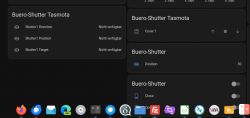
    i see a different behavior of Tasmota and Openbeken on HA.

    User interface showing Tasmota and OpenBeken settings on Home Assistant.

    I marked the Tasmota as Tasmota.
    The Tasmota buttons are matching much better the function. Its it how OB is sending its mqtt messages? How can we achieve this: up/down arrow and stop button in the middle?
  • #19 21395311
    lktrdng
    Level 4  
    Hi guys, thanks for the info in this post. I also got one of these BK7231N with CBLC9 board soldered to the main board.
    I managed to get it working, but since I was not fully confident in understanding the automations posted here (I'm new to openbeken) and I didn't want any blocking logic, I built my own and I wanted to share it with you all, maybe someone feels it useful :D.

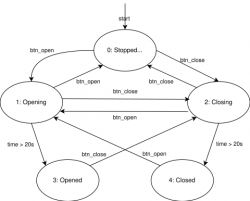
    This is the State Machine Drawing of my logic:

    State machine diagram illustrating the opening and closing logic.

    And here is the code of my autoexec.bat (I needed to create the IO channels on it just in case).
    
    // State machine
    //0: stopped/unknown position
    //1: opening
    //2: closing
    //3: stopped/opened
    //4: stopped/closed
    
    SetPinChannel 6 12
    SetPinRole 6 dInput
    SetPinChannel 7 2
    SetPinRole 7 Rel
    SetPinChannel 8 0
    SetPinRole 8 WifiLED_n
    SetPinChannel 9 1
    SetPinRole 9 Rel
    SetPinChannel 24 13
    SetPinRole 24 dInput
    SetPinChannel 26 11
    SetPinRole 26 dInput
    
    startDriver httpButtons
    setButtonEnabled 41 1
    setButtonLabel 41 Abrir
    setButtonEnabled 42 1
    setButtonLabel 42 Cerrar
    
    setChannelType 43 ReadOnly
    ClampChannel 43 0 4
    SetChannelVisible 43 0
    setChannelLabel 43 State 1
    
    alias goto-opening-then-opened backlog setChannel 2 0; setChannel 1 1; setChannel 43 1; addRepeatingEventID 20 1 1 goto-opened
    alias goto-opened backlog setChannel 1 0; setChannel 43 3
    
    alias goto-closing-then-closed backlog setChannel 1 0; setChannel 2 1; setChannel 43 2; addRepeatingEventID 20 1 2 goto-closed
    alias goto-closed backlog setChannel 2 0; setChannel 43 4
    
    alias goto-stop backlog cancelRepeatingEvent 1; cancelRepeatingEvent 2; setChannel 1 0; setChannel 2 0; setChannel 43 0
    
    //btn_open
    alias btn-open if $CH43==0||$CH43==2||$CH43==4 then goto-opening-then-opened else btn-open-cancel
    alias btn-open-cancel if $CH43==1 then goto-stop
    addChangeHandler Channel11 == 0 btn-open
    
    //btn_close
    alias btn-close if $CH43==0||$CH43==1||$CH43==3 then goto-closing-then-closed else btn-close-cancel
    alias btn-close-cancel if $CH43==2 then goto-stop
    addChangeHandler Channel12 == 0 btn-close
    
    //soft_btn_open
    setButtonCommand 41 btn-open
    
    //soft_btn_close
    setButtonCommand 42 btn-close
    
    // Schedule automatic open and close based on NTP time
    startDriver NTP
    // set local timeserver
    ntp_setServer 192.168.1.1
    // set timezone
    ntp_timeZoneOfs +3
    
    //schedule open time
    // every day except weekends (0x01 sun, 0x02 mon, 0x04 tue, 0x08 wed, 0x10 thu, 0x20 fri, 0x40 sat) > 0011.1110 = 0x3E
    addClockEvent 08:00:00 0x3e 1 btn-open
    
    //schedule close time
    addClockEvent 18:00:00 0xff 2 btn-close


    You will notice I used dInput instead of button, that's because I wasn't able to make it work otherwise :P.
    Also, the time for the curtain to be considered fully open or closed is 20 seconds, this might be adjusted depending on the real world of your implementation.

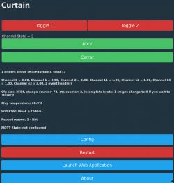
    This is the web interface:

    User interface of curtain management software with buttons and channel state.

    Basically added 3 fields:
    Channel state: Here you can check in which state the state machine is, in the screenshot is in state = 3, meaning fully opened.
    Button "Abrir": AKA soft_btn_open, to trigger the opening command.
    Button "Cerrar": AKA soft_btn_close, to trigger the closing command.
    Everything else is default

    My next step now is to automate to open/close on certain hours of the day.
    UPDATE: Added a few lines at the end of the code to open the curtain at 8am of working days and close every day at 6pm. New pendings: consider sunrise/sunset, consider daylight saving times.

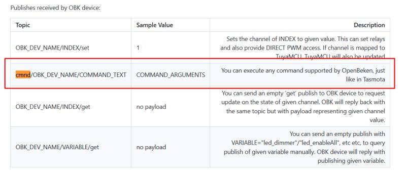
    UPDATE2: I just discovered (it might be obvious) that you could trigger the commands to open/close directly calling the aliases created, like http://deviceip/cm?cmnd=btn-open or http://deviceip/cm?cmnd=btn-close respectivelly.
  • #20 21410291
    amos2
    Level 3  
    hi
    i am new to the "OpenBK"
    i got the QS-WIFI-S10-C4 and successfully burned it with the new firmware.
    how do you change the input template?
    when i paste the one from the post it returns to an old one after some seconds
    also i see referring to "autoexec.bat" file how you use it is it on the OpenBK ?

    tnx Amos
  • #22 21410407
    amos2
    Level 3  
    hi
    after configuring the QS-WIFI-S10-C04

    I can see that the AC voltage is ~19 V on the relay when not activated
    when activated is 220
    is this normal or is it only my model?
    (I expect ~0V when the relay is off )

    the unit is not connected to the engine yet
  • #23 21628727
    vincenzoernst1
    Level 8  
    @amos2

    this is correct. there is always a small voltage. it just because its cheap hw.


    @divadiow

    another one which i use permantly now.

    can you grep the config from the 1st post (>>21049246)

    and make a PR, plz?
  • #25 21628775
    p.kaczmarek2
    Moderator Smart Home
    Interesting, it seems I got the same device from polish Allegro few days ago.
    https://github.com/openshwprojects/FlashDumps/commit/d62f39e0e9e542890117b6c126ab352c5e7d27e6
    Helpful post? Buy me a coffee.
  • #26 21628866
    vincenzoernst1
    Level 8  
    >>21628758

    THX!

Topic summary

The discussion focuses on the teardown, flashing, and configuration of the QS-WIFI-S10-C04 Mini WiFi Curtain Module based on the CBLC9 board with the BK7231N chip, similar to the RTX WCM1MR model. Users report challenges in flashing the device using OpenBK firmware and TUYA Cloud Cutter, including issues with UART communication, powering the module correctly (notably the importance of stable 3.3V supply and short wiring), and enabling AP pairing mode for flashing. The full 2MB flash backup is recommended for configuration extraction. Several users share autoexec.bat scripts and configuration templates for OpenBK, addressing relay control logic, button input handling, and shutter mode settings. Problems include simultaneous relay activation risking motor damage, improper relay toggling behavior, and input pin role inconsistencies where dInput_n works better than button mode. Comparisons between OpenBK and Tasmota MQTT messaging reveal differences in control interface behavior. The community provides detailed pin assignments, flashing procedures, and troubleshooting tips, emphasizing the need for correct power sequencing and wiring length to establish UART communication. Some users report unexpected relay voltage readings and seek clarification on normal operation. Overall, the thread serves as a technical resource for reflashing, configuring, and customizing the QS-WIFI-S10-C04 curtain module firmware and hardware interface.
Summary generated by the language model.
ADVERTISEMENT