logo elektroda
logo elektroda
X
logo elektroda

Differences in Gosund SW5 SW5-A-V2.1 PCB with BK7231N MCU and Z2-N-V1.1 Module

mtntrx 987 9
ADVERTISEMENT
  • #1 20925041
    mtntrx
    Level 2  

    I used this great teardown to get some Gosund SW5s working.
    https://www.elektroda.com/rtvforum/topic3892160.htm
    Everything worked great, but my version was a bit different.

    Before considering things I include here, read the post above. I won't repeat things here.

    My version:

    Externals:
    Gosund SW5 smart Wi-Fi switch
    Model: SW5
    Manufacturer: Shenzhen Cuco Smart Technology Co Ltd (from box)
    Date code: 11/23 and 12/23

    Internals:
    PCB: SW5-A-V2.1
    Module: Z2-N-V1.1 has other "0717" marking
    MCU: BK7231N

    Smart life app reports:
    Main Module: V1.0.1
    MCU Module: V1.0.1

    P7: LED (main, green, most visible)
    P8: Btn
    P14: Rel
    P16: LED_n 1 (red, visible through same switch window as green)
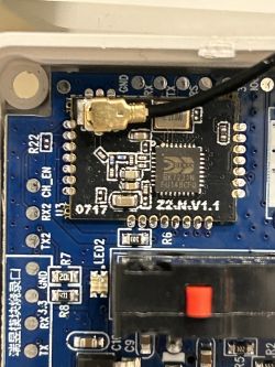
    Close-up of a circuit board featuring a Z2-N-V1.1 module and BK7231N microcontroller.

    The only real significant difference I see is the module and chipset are different. (new module version# with an N Beken chip vs. the T)

    The openBeken N firmware was available here: https://github.com/openshwprojects/OpenBK7231T_App/releases and serial flashing worked well.

    There was not a device-profile supported for this chip/firmware on tuya-cloudcutter. Cossid helped get that sorted super quick https://github.com/tuya-cloudcutter/tuya-cloudcutter/issues/598. I was able to get it flashed OTA without opening one up using this guide here: https://github.com/tuya-cloudcutter/tuya-cloudcutter/blob/main/HOST_SPECIFIC_INSTRUCTIONS.md

    I really want to get another auxiliary input working (Maybe those TX/RX TX2/RX2 pads) but I'm getting stumped as the bootloader and firmware are making use of those pins for serial programming and logging. I was able to get TX/RX freed up and working as GPIO (with a custom FW hack to the SDK source), but I'm concerned I might be messing up future serial loading capabilities. TX2/RX2 have been more resistant to my novice hacking. I want the extra input because I like using it for controlling a 3-way switch for another light with a dumb switch in the same electrical box. Anyway, I'll probably be posting for help on that soon (10 more bangs of the head on desk first)
  • ADVERTISEMENT
  • #2 20925219
    p.kaczmarek2
    Moderator Smart Home
    Well, for the start, why do you insist on using UART ports? Your module has many pads that you can solder wire to.
    Helpful post? Buy me a coffee.
  • ADVERTISEMENT
  • #3 20925308
    mtntrx
    Level 2  

    Two reasons:
    1) TX/RX and TX2/RX2 are the only ones that have the larger landing pads that are easily contactable. Those sites leaving the module are SUPER small and I don't think I can get to them reliably.
    2) I'm not 100% sure any other I/Os leave the module. I used the GPIO finder (that throws them all HIGH and LOW) and the only module pin that changed was the one in use by the relay. (and TX/RX after I got the UART shut down)
  • #4 20925342
    p.kaczmarek2
    Moderator Smart Home
    So it's a soldering issue, I see. Very well. Let's try to reuse UART ports, then.

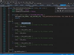
    Okay, from what I can see in the code, the UART ports protection is disabled already:
    Screenshot of code in Microsoft Visual Studio related to UART port settings.
    Why do you think that you are unable to tamper with them? I think they should work okay when you set a Relay role for them or something.
    Helpful post? Buy me a coffee.
  • #5 20925595
    mtntrx
    Level 2  
    Yes, I saw that code as well. So we know openBK is not forcefully overwriting my config to protect those pins. However, both UARTs appear to be initialized elsewhere in the code. UART1 is probably turned on in the SDK by default. UART2 is turned on for logging and I think that might be a conflict too.

    1) Initially, neither set (TX/RX nor TX2/RX2) responded to a config setting them as outputs) "Rel_n 4 to 7"
    2) after hacking this in platforms/bk7231n/bk7231n_os/beken378/driver/uart/uart.h, I was able to get TX and RX to work and respond as a "Rel_n" outputs
    Code: C / C++
    Log in, to see the code


    So, while I wasn't able to free up TX2/RX2, it did tell me that UART conflicts can prevent these things from work as desired.... I think

    There is some UART init stuff going on in cmd_main.c, and src/driver/drv_uart.c but I haven't had any luck messing in there... yet.

    I plan to experiment and see if using TX/RX as inputs, and having them tied either low or high at boot screws anything up. I'm thinking the high/low connection could potentially cause issues as the boot loader will be looking at that interface for a split sec at boot.

    Thanks for the help and ideas.
  • ADVERTISEMENT
  • #6 20925622
    p.kaczmarek2
    Moderator Smart Home
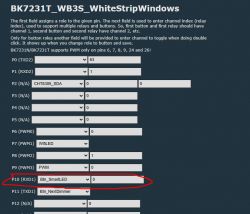
    First of all, I must admit that I am confused. Even my light strip that I use daily has a button on RXD1 and it works for 3 years already:
    Screenshot of BK7231T settings with pin configuration.

    But still, if you think that something overwrites your settings, try autoexec.bat with:
    
    delay_s 5 
    SetPinRole 0 LED
    SetPinRole 0 Rel
    

    The following code first waits 5 seconds, then sets pin role to LED, and then, right after, sets it to Rel, this is done in order to force a change (because setting the same state might be culled by firmware).
    Helpful post? Buy me a coffee.
  • ADVERTISEMENT
  • #7 20925626
    mtntrx
    Level 2  

    That's good to know. Is that a BK7231N with OpenBK? That tells me I might need to do some more in-depth testing. I can scope it as well.
  • #8 20925629
    p.kaczmarek2
    Moderator Smart Home
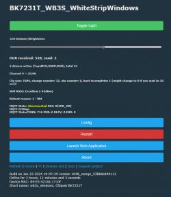
    This is current version:
    Screenshot of the LED lighting management interface for BK7231T.
    I update it every week or two and it always works.

    Btw, you can also search templates to check which devices are using P0, etc, for some role:
    https://github.com/OpenBekenIOT/webapp/blob/gh-pages/devices.json
    Helpful post? Buy me a coffee.
  • #9 21174450
    quedan
    Level 1  
    >>20925041 Sorry to necro this a bit but, I have a different Gosund product, a P2 outlet splitter. It comes with the module and MCU you have on your SW5 but with a newer version of firmware (1.0.5) in my case.
    I'm having a really hard time getting the chip into flash mode (i.e. have not been successful) so I'm wondering if you might be able to offer some tips etc. on how you got yours into flash mode.
  • #10 21176240
    p.kaczmarek2
    Moderator Smart Home
    Are you saying that your device has both WiFi module and external MCU? So you've got TuyaMCU device?
    TuyaMCU guide: https://www.elektroda.com/rtvforum/topic4038151.html

    Or do you refer to Beken itself as "MCU"?
    Helpful post? Buy me a coffee.

Topic summary

The discussion revolves around the differences in the Gosund SW5 smart Wi-Fi switch, specifically the SW5-A-V2.1 PCB with a BK7231N MCU and the Z2-N-V1.1 module. The user successfully modified their device using a teardown guide but noted discrepancies in the module and chipset compared to other versions. Key points include challenges with UART port usage due to small landing pads and potential conflicts in the firmware affecting pin roles. Suggestions for troubleshooting include using specific commands in the autoexec.bat file to set pin roles and exploring the OpenBK firmware for better control. Another user shared their experience with a different Gosund product, seeking advice on entering flash mode for firmware updates.
Summary generated by the language model.
ADVERTISEMENT