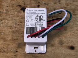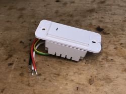
Hello, here I will present the short teardown and OpenBeken programming guide for Gosund Smart Switch SW5-A-V2.1 with an unusual BK7231T module inside, which I am going to desolder with hot air in order to make high res photo of pad. The switch was donated to me by Jennifer from USA - thank you!
Package from Jennifer
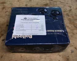
The package was sent to me from the US on March 22 via the USPS (US Postal Service). It was marked as "Gifts", declared value 0.5 $.
The postman brought it to me on May 4, I had to pay PLN 8.5 of the postage:


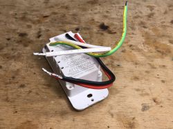
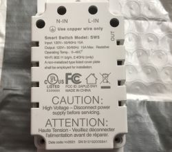
This is not the first time such a fee. For the package with garden double plug with BK7231T from @strigona , I also had to pay PLN 8.5.
Without delay, I started disassembling it.
The interior of Gosund Smart Switch SW5-A-V2.1
The housing is held by four screws. After that, you can remove the back plate.
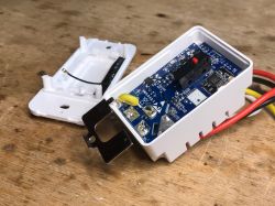
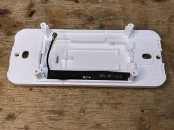
Here you can see something unusual, an external 2.4GHz WiFi antenna. It's not usually used, modules like ESP12F (TYWE3S), TYWE2S, WB2S or WB3S (regular) don't have it.
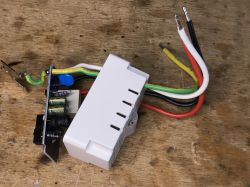
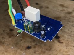
Fusible resistor, a filter from two 400V 3.3uF capacitors (by the way - 400V in a switch for 120V? 120V mains is used in USA, and in Poland I have 230V mains) and a choke (the green one), a large choke (black) from a transformerless power supply ...
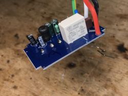
Interesting fact - this 16A fuse, more precisely 16A250V, protects the entire system and the lamp connected via the relay. This fuse is directly connected to the L-in. I don't see such things in other smart switches, there is usually only a fusible resistor that protects the power supply only, not the relay light bulb.
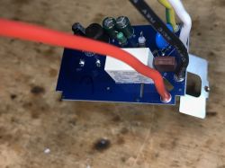
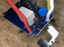
Here you can see the MB10F rectifier bridge, followed by the already mentioned Pi filter, and a bit further the transformerless converter controller powered by some SMD chip with IADGN label:
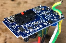
IADGN is an SMD code, I don't know the full part name, but I can see you can buy replacement easily:

Next you see the LDO regulator AMS 1117 3.3V (it provides 3.3V for the WiFi module) and you can also see the decicated programming and debugging pads. They will be useful for us:
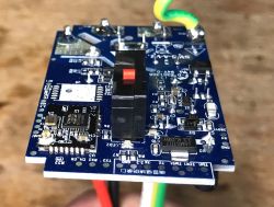
On the other side, there is also a transistor marked 1AM (probably MMBT3904) that activates the relay together with a "free-wheeling diode" SMD 7A diode connected in parallel to the relay coil, removing sudden voltage spikes when switching.
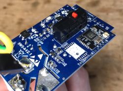
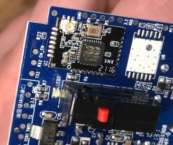
There is room here for an alternative WiFi module. Does anyone know which module fits here?
Programming Gosund Smart Switch SW5-A-V2.1
The procedure turned out to be very simple.
Same as here:
Garden Tuya CCWFIO232PK Double Relay - BK7231T - Programming
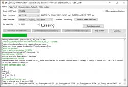
Just connect 5V to the AMS1117-3.3V input from a separate power supply in order to be able to reboot the system (cut off the power for a moment) without overloading the USB port with inrush current spike, connect RX and TX from the USB to UART converter based on CH340 in 3.3V mode and connect all ground signals together.
I used a USB cable to connect the second 5V (it was a micro USB, but the connector was damaged so I cut it off):
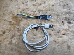
Soldering the 5V power supply (thanks to the 5V power supply, the relay will also work, which will allow us to immediately determine which pin it is connected to, by testing the pins again):
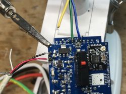
RX and TX wires soldering:
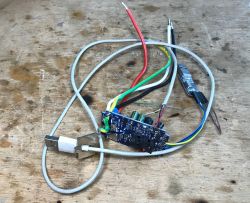
The programming procedure is as follows:
1. in bkWriter 1.60 run read or write
2. Disconnect the 5V power supply for a while, reconnect it
3. bkWriter should start reading or writingthe firmware
Sometimes it takes several tries to get it right, it's also worth checking different baud rates.
Configuration in OpenBK
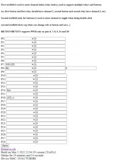
This switch has quite a rich pin configuration options. It has a separate green LED which can be used to show WiFi status, a separate red LED for relay state, a button and a relay. Other manufacturers combine the signal controlling one diode and the relay together, but this is not the case here. So you can choose whether, for example, the red diode will be lit when the relay is turned off or if the relay is turned on. I personally prefer that it is lit when relay is turned off, because then at night it is easier to find the switch.
Final pin configuration:
An example of scripting a switch and a light in OpenBeken
I think it is worth showing the additional possibility that I recently implemented in my OpenBeken.
Prelimary event scripting and command systems have been added as an alternative to automation and scenarios found in Tuya or there in Home Assistant. My scripting system does not require an external server.
So, for a demonstration, we just need:
- a Smart WiFi bulb with OpenBeken (but Tasmota will also be compatible!) with IP reservation made on the router
- a switch, just like the one from this topic
First, we reserve our IP lamp in the router settings:

Then, on the switch, we have to set the so-called "event handler", ie handling the event on the button device.
The following command is used for this:
setEventHandler [EventName] [Argument] [Command]
For example, for clicking a button on pin 8:
addEventHandler OnClick 8 [Command]
(pin 8 must have the role Button set)
As "command" we want to send the POWER state switching command via Tasmota HTTP (OpenBeken supports this protocol) to the IP address of the lamp.
Sending such a command looks like this (you can try to call it from the OpenBeken console):
SendGet http://192.168.0.112/cm?cmnd=Power0%20Toggle
So, the complete command for handling an event with sending a Power Toggle looks like this:
addEventHandler OnClick 8 SendGet http://192.168.0.112/cm?cmnd=Power0%20Toggle
You can type this in the console, but then it won't save and the event handler will be lost after rebooting the device.
For this reason, it's better to set it up in one of the two available places.
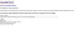
1.as "short startup command" in Config (up to 512 characters, you can give many commands there by using the backlog - syntax like in Tasmota)
2. as a command from the "autoexec.bat" file in LittleFS in the OpenBK JS panel
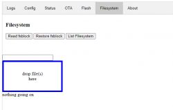
(to create a file, drag it to the field "drop file here". Then you can edit it from the browser. LittleFS at the moment is cleared during OTA execution, so you should have a copy of the files)
Demonstration:
[video: ce9be6a240] https://filmy.elektroda.pl/7_1652038982.mp4 [/ video: ce9be6a240]
It works. This is a substitute for "Tasmota Group", which will also be supported by me soon.
Module identification with BK7231T
I also decided that it is still worth identifying what specific module is in this device.
It is not marked on the outside, so I was not able to identify it without desoldering.
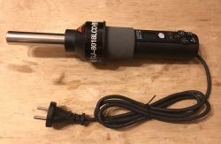
The pad markings must be on the bottom silkscreen, so I decided to unsolder the module with hot air gun (GJ-8018LCD):
First, I also desoldered the button so as not to melt it.
In order to make desoldering easier, I added lead tin and flux:
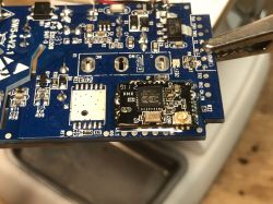
Ready, after long and even heating:
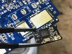
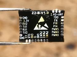
The module turns out to be Z2-B-V1.0. Here is the silk screen photo:
Before soldering it back in place, I cleaned the PCB and pads:
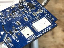
During soldering:
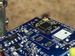
After soldering it back in place, the switch is still working.
Summary
Thanks again @echojjj for sending me this switch for review. It was really interesting!
Programming with OpenBeken turned out to be very easy as all required signals are routed out to the pads.
The switch turned out to be useful even in Poland, because it works on 230V (I checked in practice).
The BK module from inside turned out to be a novelty for me, even the search engine is silent when I enter "Z2-B-V1.0", and thanks to desoldering it from the board, I got to know the role of its outputs, which may be useful in the future when reworking other devices.
By the way, I also presented a simple automation in OpenBeken, which can be implemented without the need to involve an external Home Assistant server.
PS: Is this Z2-B-V1.0 footprint not compatible with some ESP module, maybe ESP32? I haven't had time to check yet, but maybe someone knows?
Cool? Ranking DIY Helpful post? Buy me a coffee.


