logo elektroda
logo elektroda
X
logo elektroda
ADVERTISEMENT
  • There has been many versions of Mini Smart Switch.
    1. Aubess 2gang Mini Smart Switch BK7231N /CB2S
    2. mini smart switch - Belon BL2028N-
    3. ZN268131 WB2S BK7231T WiFi Smart Switch that allows you to connect a bistable button

    4. Cheapest Wi-Fi Switch You Can Buy For Your Smart Home


    I came across another product which has diferrent internals but with CB2S/BK7321N.
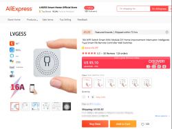
    Mini Smart Switch - CB2S BK7231N Based


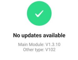
    Software version was V1.3.8

    I tried tuya-cloudcutter with many different profiles for BK7321N but was not successful.

    Manual Flashing was the only way forward.

    1. Opening the device was very easy. I used several guitar picks to release the tabs on the four corners.
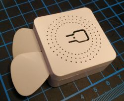
    Mini Smart Switch - CB2S BK7231N Based

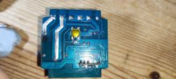
    2. There were two daughter boards with CB2S module connected to a shorter daughter board (very similar to attaching the WB2S module in link 3 above)
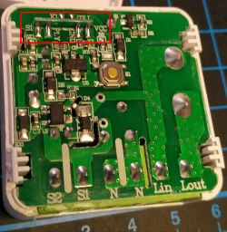
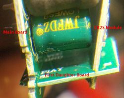
    Mini Smart Switch - CB2S BK7231N Based

    Mini Smart Switch - CB2S BK7231N Based

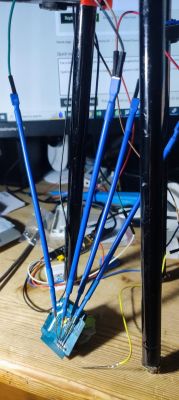
    3. Instead of soldering wires I have decided to try out a different method to secure jumper wires to the soldering pads mechanically using custom made clips like these
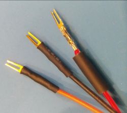
    Mini Smart Switch - CB2S BK7231N Based

    I made these by removing the pins from a female header connector and then crimping the fork like metal pin to a female jumper wire connector as shown.

    4. Plan of the connections
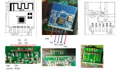
    Mini Smart Switch - CB2S BK7231N Based

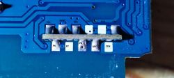
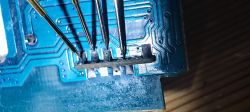
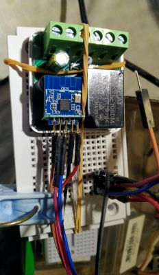
    5. Since the CB2S module has pins on both sides which are arranged as alternate slots, my attachments can be secured so that only one side is touching a pin. However one has to be careful not to let the pin touch adjacent solder pads on either side.
    Mini Smart Switch - CB2S BK7231N Based

    The leftmost pin touches the solder pad on the top side of the PCB while the rightmost 4 pins touches TX1, RX1, GND and 3V3 solder pads on the bottom side.

    BTW, the TX1, RX1 pins have no connections to the daughter board. So no worry about removing the CB2S module for flashing.

    6. Used python uartprogram for flashing

    During dumping the existing firmware use of default high speed baudrate was successful. I used option to lower the baudrate to a very very low value and it was successful but took a way long time.

    Flashing new firmware at default baudrate was successful.

    Cool? Ranking DIY
    About Author
    jkwim
    Level 12  
    Offline 
    jkwim wrote 169 posts with rating 23, helped 4 times. Been with us since 2022 year.
  • ADVERTISEMENT
  • #2 20359572
    p.kaczmarek2
    Moderator Smart Home
    Very good presentation, but it's important to add one more note here.
    Those cheapest box switches have a very weak power supplies with low quality electrolytic capacitors. I even covered replacement of such capacitor here:
    https://www.elektroda.pl/rtvforum/topic3898805.html
    There is one way to increase the life of power supply and also the stability of WiFi module.
    To your autoexec.bat (or to short startup command) add PowerSave command.
    This will enable extra low power consumption mode for BK7231T/BK7231N and reduce the current consumption and heating.

    NOTE: in the future it may be enabled by default, but it's still at testing phrase

    Also note: some of similar devices are using RX/TX pin of CB2S/WB2S to control button or a relay, so it might be easier to just desolder whole WiFi module and program it outside of the board.
    Mini Smart Switch - CB2S BK7231N Based
    The image above shows WB2L_M1 but it's similar for WB2S and CB2S
    Helpful post? Buy me a coffee.
  • ADVERTISEMENT
  • #3 20853216
    divadiow
    Level 34  
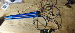
    I've a similar mini switch with CB2S but not a riser/daughterboard. I've confirmed continuity between usb-serial pins and the end of my pogo pins, and the unit is powering so ground and vcc are fine.

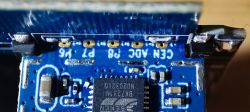
    I just cannot get touching CEN to begin acknowledgment in BK Easyflasher, however long I hold CEN connected. Did you have any difficulty with yours @jkwim ?

    also, with the power off/on method - how do you do this without interrupting the com port? mine drops out of device manager and BKflasher just stops with no com port error.

    Close-up of a circuit board with labeled solder points VCC, GND, RX1, TX1, P24, P26, P6, P7, P8, ADC, and CEN.
    Electronic circuit board with a yellow button on a wooden background.
    Wiring connections with an electronic module on a desk. Close-up of a circuit board with several connected pogo pins.
    Screenshot displaying No updates available message, indicating Main Module version V1.3.10 and Other type V102.
    Close-up of a circuit board with visible pins labeled CEN and ADC on a blue background. Mini smart switch with a power-off icon and Common Functions label.
  • #4 20853221
    p.kaczmarek2
    Moderator Smart Home
    COM port should never drop, how do you power that? COM may drop if there is a large capacitance on the device and you power it via 5V to the 3.3V LDO on the device board, that's why I usually just desolder the WiFi module. I don't even use CEN, I just do power off/on cycle.
    Also, your wires seem long, this may cause flashing problems.
    Helpful post? Buy me a coffee.
  • ADVERTISEMENT
  • #5 20853248
    divadiow
    Level 34  
    >>20853216

    hello! thanks for replying so quickly.

    it's just 3.3v from the usb-serial adaptor, not via 5v or anything. I was trying to avoid desoldering because I'm not convinced I'll get it back in again!

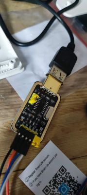
    it's possible the wires are too long, I've had to join two jumper wires for each pogo pin to the usb device. I need more male-female. I could try shorter with what I have.

    not sure why the com port is dropping. I am only disconnecting the power pin from the usb adaptor end when I do power cycle :(

    I don't have a breadboard, but surely removing and reinserting into a breadboard is the same as disconnecting from usb-serial...

    Electrical wires connected to a USB-serial adapter on a wooden surface. USB-Serial adapter connected to wires on a wooden table.
  • #6 20853276
    p.kaczmarek2
    Moderator Smart Home
    Have you watched our tutorials?
    https://www.youtube.com/@elektrodacom
    It's been stated many times that USB to UART adapter will not provide enough current and it's recommended to use external one. Or at least a better one, like a 3.3V from Arduino, which can be used also as USB to UART converter as long as you put Atmega in RESET state
    Helpful post? Buy me a coffee.
  • ADVERTISEMENT
  • #7 20853320
    divadiow
    Level 34  
    I've seen a few vids now yes, and I do recall that being stated. I need more equipment! I was just hopeful that if the device is powering and I can pair with Tuya that that would be enough current to flash. I'll go shopping and try again.
  • #8 20853328
    p.kaczmarek2
    Moderator Smart Home
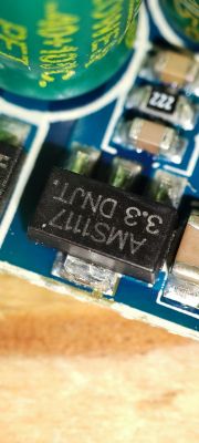
    Maybe that's not needed. Is there an AMS1117-3.3V visible on your board?

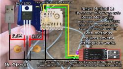
    It is possible to connect 5V from USB to the input of that AMS1117-3.3V LDO and reset via disconnecting that 5V connection.
    Helpful post? Buy me a coffee.
  • #9 20853335
    divadiow
    Level 34  
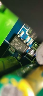
    Yes, there is an AMS and a BP

    Close-up of an electronic component marked as BP2525 on a circuit board.
    Close-up of electronic components on a printed circuit board, including a black chip labeled AMS1117 3.3 DNLT.
  • #10 20853381
    p.kaczmarek2
    Moderator Smart Home
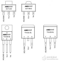
    Here is AMS pinout:
    Pinout examples of AMS1117 in SOT-223, SOT-89-3, TO-220-3L, TO-252-2L, TO-263-3L packages.
    You can flash your device by soldering GND, 5V from USB, RX and TX . Then you power off/on by disconnecting 5V.
    Helpful post? Buy me a coffee.
  • #11 20855897
    divadiow
    Level 34  
    thank you. I got this yesterday so could have a separate 3.3v and some more male-female wires (and a 10k resistor for BL602 in the future). Yes my external 3.3 and usb-ttl are connected for common ground.

    https://www.amazon.co.uk/dp/B01ERP6WL4

    curiously, there is still no flashing it seems. My wires are now single length between each leg. I've tried 3 different USB-TTL adaptors (CH340 and 2x (probably fake) FTDI). Nothing after CEN or powering on/off 3.3v (COM port no longer drops when external 3.3v is switched).

    I saw in this thread https://www.elektroda.com/rtvforum/topic3977701.html from @erlipan2001 that they updated the original post to warn of RX being grounded, but I do not have continuity to ground with the RX on this device, so don't think it's that (assuming there would be continuity if it was this issue?). There is no power monitoring chip.

    I've tried 115200 and 9600 baud. I'm guessing my next step can only be unsoldering the board. Or trying hid_download_py
  • #12 20855927
    p.kaczmarek2
    Moderator Smart Home
    Unsoldering WiFi board is a very reliable method and it's more easier than it seems. Just make sure to use some flux and solder wick.
    Helpful post? Buy me a coffee.
  • #13 20857170
    divadiow
    Level 34  
    woohoo. finally did it. it was actually the RX in the end. unsoldered it with wick and flux and it flashed straight away to OpenBeken.

    
    {
    	"nc_tp":"1",
    	"ssid":"null",
    	"passwd":"null",
    	"md":"0",
    	"random":"0",
    	"wfb64":"1",
    	"stat":"0",
    	"token":"null",
    	"region":"null",
    	"reg_key":"null",
    	"dns_prio":"0 }{nc_tp",
    	"psk_key":"vJP0jKnMmU4d6lwLNfLylG1oSPqnuHq3etjmf",
    	"auth_key":"nr4RxVwLp8HPDSbmojIw5bLIpizkytEE",
    	"ap_ssid":"SmartLife",
    	"ap_passwd":"null",
    	"country_code":"CN",
    	"bt_mac":"null",
    	"bt_hid":"null",
    	"prod_test":"false",
    	"fac_pin":"vs4ksbpax2dwwm6a }-B000004re0c[{type",
    	"mode":"rw",
    	"property":"{type",
    	"id":"1}",
    	"{type":"obj",
    	"max":"86400",
    	"scale":"0",
    	"step":"1",
    	"type":"value}",
    	"maxlen":"255}",
    	"{mode":"rw",
    	"lckey":"3]bmXI;?9@Xl7.a1",
    	"h_url":"http",
    	"h_ip":"3.123.188.102",
    	"hs_url":"null",
    	"hs_ip":"null",
    	"hs_psk":"https",
    	"hs_psk_ip":"18.195.249.137",
    	"mqs_url":"null",
    	"mqs_ip":"null",
    	"mq_url":"m2.tuyaeu.com",
    	"mq_ip":"35.156.42.116",
    	"ai_sp":"null",
    	"ai_sp_ip":"null",
    	"mq_psk":"m2.tuyaeu.com",
    	"mq_psk_ip":"35.156.42.116",
    	"lp_url":"baal.tuyaeu.com",
    	"lp_ip":"18.193.97.90",
    	"time_z":"+00",
    	"s_time_z":"[[1711846800",
    	"wx_app_id":"null",
    	"wx_uuid":"null",
    	"dy_tls_m":"0",
    	"cloud_cap":"1025",
    	"psk21_key":"null }{nc_tp",
    	"on_off_cnt":"10",
    	"onoff_rst_m":"1",
    	"onoff_clear_t":"10",
    	"rand_dpid":"42",
    	"net_trig":"4",
    	"onoff_n":"5",
    	"netled1_lv":"0",
    	"jv":"102",
    	"onoff_rst_type":"2",
    	"total_bt_pin":"10",
    	"nety_led":"2",
    	"total_stat":"2",
    	"reset_t":"5",
    	"netled1_pin":"8",
    	"remote_add_dp":"49",
    	"remote_list_dp":"50",
    	"net_type":"0",
    	"inch_dp":"44",
    	"module":"CB2S",
    	"ch_cddpid1":"9",
    	"onoff1":"23",
    	"clean_t":"5",
    	"init_conf":"38",
    	"zero_select":"0",
    	"onoff_type":"0",
    	"series_ctrl":"0",
    	"total_bt_lv":"0",
    	"cyc_dpid":"43",
    	"remote_select":"0",
    	"ch_num":"1",
    	"rl1_pin":"26",
    	"netn_led":"0",
    	"ch_dpid1":"1",
    	"crc":"94",
    	"}#FBble_beaconkeyAADBFDB6AB2A9B5D01FFEA91EB8728B9{abi":"0",
    	"swv":"1.3.10",
    	"bv":"40.00",
    	"pv":"2.2",
    	"lpv":"3.4",
    	"pk":"keyjnuy4s3kre7m7",
    	"firmk":"keyjnuy4s3kre7m7",
    	"cadv":"1.0.5",
    	"cdv":"1.0.0",
    	"dev_swv":"1.3.10",
    	"s_id":"000004re0c",
    	"dtp":"0",
    	"sync":"0",
    	"attr_num":"1",
    	"mst_tp_0":"100",
    	"mst_ver_0":"102",
    	"mst_md5_0":"f314a40ea88403776ca006c24647bb7b",
    	"mst_tp_1":"0",
    	"mst_ver_1":"null",
    	"mst_md5_1":"null",
    	"mst_tp_2":"0",
    	"mst_ver_2":"null",
    	"mst_md5_2":"null",
    	"mst_tp_3":"0",
    	"mst_ver_3":"null",
    	"mst_md5_3":"null }{key",
    	"index":"0}{ch0",
    	"cnt":"0}0$6Bis_stride0{abi",
    	"ap_s{nc_tp":"1",
    	"mst_md5_0{ch0":"0}1",
    	"mst_3ch0":"0}1"
    }


    Device configuration, as extracted from Tuya: 
    - Pair/Toggle All Button on P10
    - WiFi LED on P8
    - TglChannelToggle (channel 1) on P23
    - Relay (channel 1) on P26
    Device seems to be using CB2S module, which is using BK7231N.
    And the Tuya section starts, as usual, at 2023424


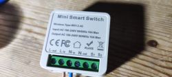
    Mini Smart Switch with visible technical markings and wire terminals.

    not the tidiest, but hey.
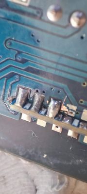
    Close-up of a circuit board with soldered pins.

Topic summary

The discussion revolves around various models of Mini Smart Switches based on the BK7231N/CB2S chipset, including the Aubess 2gang Mini Smart Switch, Belon BL2028N, and ZN268131 WB2S. Users share experiences with flashing firmware, troubleshooting connectivity issues, and the importance of using quality power supplies to enhance device stability. Manual flashing is often necessary due to difficulties with tools like Tuya-cloudcutter. Participants discuss the significance of proper wiring, the use of external power sources, and the potential need to desolder components for successful firmware updates. A successful flashing to OpenBeken firmware was achieved after addressing RX pin issues.
Summary generated by the language model.
ADVERTISEMENT