logo elektroda
logo elektroda
X
logo elektroda

Flashing Geeni Current + Charge with OpenBK on WB2S Module

zac1 783 10
ADVERTISEMENT
  • #1 20932022
    zac1
    Level 2  
    Hi folks,
    I have a few of these Geeni Current + Charge outlets, and I'm going to attempt to get OpenBK on them.
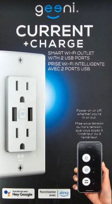
    Packaging of Geeni Current + Charge outlet with USB ports.

    I've pulled the thing apart, and it looks like it's a WB2S module.
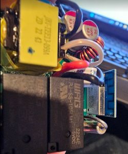
    Close-up of the inside of a Geeni Current + Charge smart outlet with a visible WB2S module.
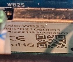
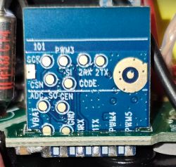
    Close-up of the WB2S module with model and serial number markings. Close-up of a WB2S electronic module with visible pins and printed labels.

    Going to probe around a bit to see if I can figure out which pins to use for flashing - but guessing that the RX2 and TX2 pins will be the business.
    Will update as I progress!

    (Impetus for the hacking is that we recently had an internet outage, and we were unable to control the plugs. Hilarious! So now I'm going to look at doing a more direct integration with HASS, bypassing the whole Tuya cloud stuff.)
  • ADVERTISEMENT
  • #2 20932547
    p.kaczmarek2
    Moderator Smart Home
    Welcome to forum. On Beken platform, we use TX1/RX1 for flashing, see our flash tool readme:
    https://github.com/openshwprojects/BK7231GUIFlashTool
    See our tutorials here:
    https://www.youtube.com/@elektrodacom/videos
    Sample tutorial for CB2S (WB2S is similiar):


    Keep in mind that you can also flash WB2S in-circuit, as long as RX1/TX1 are not used for anything on the board and you power the board correctly from a safe power supply, for example, by providing 5V at the input of on-board AMS1117-3.3V LDO. Do not connect board to mains while flashing.
    Helpful post? Buy me a coffee.
  • #3 20932600
    zac1
    Level 2  

    Thanks!

    I am getting console output on tx2/rx2, and I don't think tx1/rx1 is used for anything - it's soldered to the board, but I don't see any leads connected to it. Looks like just the GPIOs and power have leads on the PCB - so good sign, I think!

    And yeah, not putting it anywhere near mains power till it's all put back together. I don't want to die. :)
  • ADVERTISEMENT
  • #4 20932607
    p.kaczmarek2
    Moderator Smart Home
    Our flasher should be able to detect GPIO from the 2MB flash dump in most cases. Btw, if you want, please consider posting 2MB firmware backup here as well, it may come useful someday.
    Helpful post? Buy me a coffee.
  • #5 20935622
    zac1
    Level 2  
    My soldering skills are so weak, lol! But, I finally got some patch wires soldered to the appropriate pads/pins.

    Stock firmware attached.

    Going to try flashing the new firmware now - wish me luck! Thanks for the help!

    Extracted Tuya config:
    Device configuration, as extracted from Tuya: 
    - Relay (channel 3) on P6
    - Pair/Toggle All Button on P24
    - Relay (channel 2) on P7
    - Relay (channel 1) on P8
    Device seems to be using WB2S module, which is using BK7231T.
    And the Tuya section starts, as usual, at 2023424


    Also got this JSON config:
    {
    	"rl1_lv":"1",
    	"netled_lv":"0",
    	"bt_type":"0",
    	"rl3_pin":"6",
    	"rl3_lv":"1",
    	"rand_dpid":"43",
    	"net_trig":"4",
    	"led_dp":"40",
    	"jv":"1.1.0",
    	"lock_dp":"41",
    	"total_bt_pin":"24",
    	"netled_":"qBgw_wsmpin",
    	"total_stat":"2",
    	"reset_t":"3",
    	"rl2_lv":"1",
    	"ch_flag1":"1",
    	"ch_flag2":"1",
    	"ch_flag3":"1",
    	"inch_dp":"44",
    	"module":"WB2S",
    	"ch_cddpid1":"9",
    	"init_conf":"38",
    	"rl2_pin":"7",
    	"ch_cddpid2":"10",
    	"ch_cddpid3":"11",
    	"total_bt_lv":"0",
    	"cyc_dpid":"42",
    	"ch_num":"3",
    	"reuse_led_m":"1",
    	"rl1_pin":"8",
    	"ch_dpid3":"3",
    	"ch_dpid1":"1",
    	"ch_dpid2":"2",
    	"crc":"68",
    	"}uid":"f9818e028a68595f",
    	"psk_key":"gzT0zYCNcN1moK1jBclJlUaxA41KWB17ws5Vm",
    	"auth_key":"izjZJNmrDAqiFL8IikOfUN9NMRNA4FUD",
    	"ap_s@Cgw_diountry_code":"null",
    	"bt_mac":"null",
    	"bt_hid":"null",
    	"prod_test":"false "
    }
    
  • ADVERTISEMENT
  • #6 20938449
    zac1
    Level 2  
    Great success!
    Outlet is now online, reporting in to HA via MQTT, and is fully controllable.

    Now just have to do the other ones I have installed and I'll be free of Tuya's cloud!
  • #7 20990224
    p.kaczmarek2
    Moderator Smart Home
    Here is OBK template:
    Code: JSON
    Log in, to see the code
    Helpful post? Buy me a coffee.
  • ADVERTISEMENT
  • #8 21049220
    123qweasd1
    Level 3  

    p.kaczmarek2 wrote:
    https://www.elektroda.com/rtvforum/topic4031764.html


    Thanks for the work on this device;
    Looking to buy some of these units to power Home Assistant wall tablets and manage USB charging to protect the batteries.
    Some questions:

    I understand you didn't have to desolder the WB2S (kept in circuit) right?
    Would you mind confirming which connections/pinout used on device/programmer?

    Are the USB ports controlled by their own relay (common relay for both USB ports or separate)?
    Same question for 120v outlets.

    Thank you!
  • #9 21050044
    p.kaczmarek2
    Moderator Smart Home
    123qweasd1 wrote:

    Are the USB ports controlled by their own relay (common relay for both USB ports or separate)?

    Extracted config shows 3 channels, so 2 relays for mains and one toggle for all USB ports together.


    123qweasd1 wrote:

    Would you mind confirming which connections/pinout used on device/programmer?

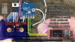
    Have you watched tutorial?
    Electronic setup showing configuration and connections for USB to TTL communication.


    123qweasd1 wrote:

    understand you didn't have to desolder the WB2S (kept in circuit) right?

    Usually WB2S does not have to be desoldered, but it depends on the device. I am not sure about that one from post.
    Helpful post? Buy me a coffee.
  • #10 21052347
    123qweasd1
    Level 3  

    Thanks for the feedback and guidelines.

    @zac1, would you mind confirming if you had to desolder or proceeded "in circuit" ?

    Thx
  • #11 21052468
    p.kaczmarek2
    Moderator Smart Home
    I would say that most likely he didn't because RX1 is P10 and TX1 is P11 and they don't seem to be used in the template:
    Screenshot of a table showing information about I/O ports.
    Helpful post? Buy me a coffee.

Topic summary

The discussion revolves around flashing the Geeni Current + Charge outlets using the OpenBK firmware on the WB2S module. The user initially inquired about the correct pins for flashing, suspecting RX2 and TX2 would be appropriate. Responses indicated that TX1/RX1 are typically used for flashing, but the user successfully received console output on TX2/RX2. After soldering patch wires to the necessary pins, the user reported successful flashing of the firmware, enabling control via Home Assistant (HA) through MQTT, thus eliminating reliance on Tuya's cloud services. Additional insights included the device's configuration, which revealed multiple relays for controlling USB ports and mains outlets. The community provided guidance on flashing techniques and device configurations, emphasizing safety during the process.
Summary generated by the language model.
ADVERTISEMENT