CB2S Dual switch module
I bought an unbranded double smart switch from Aliexpress:
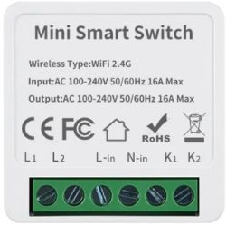
https://it.aliexpress.com/item/10050057250229...t_main.31.21ef3696NSIW01&gatewayAdapt=glo2ita
In a short time the item arrived but with wrong manual (it is related to a single switch where the S1 and S2 must be used to turn on/off the connected device) so at the moment I do not know if I must apply a phase (L) or neutral (N) to the K1 and K2 plug.
Here some picture:
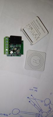
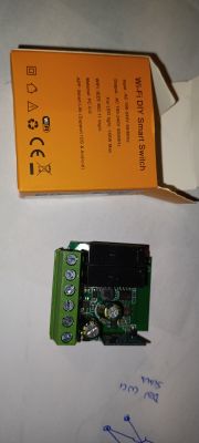
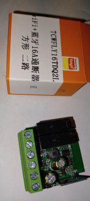
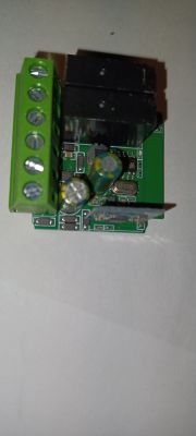
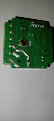
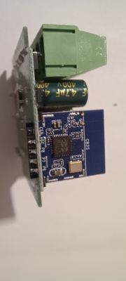
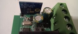
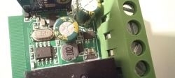
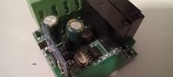
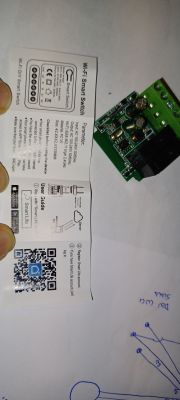
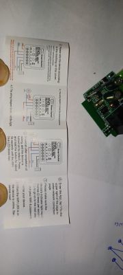
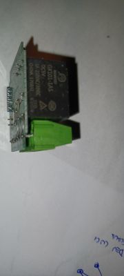
Anyway, I haven't connect it to Chinese server and immediately I re-flash the device with this beautiful firmware (I done it with other devices). In order to do it I cut the tx signal from the board and with this modification I was able to replace the firmware without de-solder the CB2S board.
The flash program was unable to identify the pins so I tried to find the functions with the GPIO finder menù: I found the two relè, the led and the button on the device. At the moment I do not risk to burn the device using a wrong command (L or N) to K1 and K2 plug, so I can't identify the right input but selecting the connected CB2S pins to the board as "input" sometimes cause the relè to switch on/off.
Looking to the board I saw that there is a 480RA chip that I understood is a RF chip; it can be possible that this device has got RF capability? If yes, it is possible to understand the functionality with the original firmware?
Someone has got the same device and can tell me if I can use the L signal to K1 and K2?
Thanks.
Luca
I bought an unbranded double smart switch from Aliexpress:

https://it.aliexpress.com/item/10050057250229...t_main.31.21ef3696NSIW01&gatewayAdapt=glo2ita
In a short time the item arrived but with wrong manual (it is related to a single switch where the S1 and S2 must be used to turn on/off the connected device) so at the moment I do not know if I must apply a phase (L) or neutral (N) to the K1 and K2 plug.
Here some picture:


Anyway, I haven't connect it to Chinese server and immediately I re-flash the device with this beautiful firmware (I done it with other devices). In order to do it I cut the tx signal from the board and with this modification I was able to replace the firmware without de-solder the CB2S board.
The flash program was unable to identify the pins so I tried to find the functions with the GPIO finder menù: I found the two relè, the led and the button on the device. At the moment I do not risk to burn the device using a wrong command (L or N) to K1 and K2 plug, so I can't identify the right input but selecting the connected CB2S pins to the board as "input" sometimes cause the relè to switch on/off.
Looking to the board I saw that there is a 480RA chip that I understood is a RF chip; it can be possible that this device has got RF capability? If yes, it is possible to understand the functionality with the original firmware?
Someone has got the same device and can tell me if I can use the L signal to K1 and K2?
Thanks.
Luca


