logo elektroda
logo elektroda
X
logo elektroda

Which light switch for the Home Assistant? Single touch Blow 72-087, we flash CB3S

p.kaczmarek2 1497 39
ADVERTISEMENT
Treść została przetłumaczona polish » english Zobacz oryginalną wersję tematu
📢 Listen (AI):
  • Close-up image of the inside of a light switch showing the PCB and CB3S module. .
    Here is another product that, after a firmware change, can be run 100% locally and linked to Home Assistant. This time it's a single light switch, appearing under vendor code 72-087#, but related models may also have designations: DS-101, DS-111, DS-151, DS-161, DS-1011ZC. Firmware is uploaded as usual via UART.

    I got the product in a kit from a reader - I was changing the firmware for him at his request in exchange for the opportunity to take photos. I received a whole series of these gadgets, but for now we will discuss the switch. The whole set can be bought for a few dozen zlotys (from China you can even order for 30 zlotys, in our country more like 60):
    Packaging of Blow smart WiFi light switch with labels. .
    Packaging of a single light switch with technical specifications. .
    Light switch packaging with model and function markings. .
    Included is a capacitor, referred to rather oddly by the vendors as an 'adapter', and an instruction manual:
    Smart WiFi light switch with accessories in a box. .
    The manual is in our language, the seller has already taken care of that:
    User manual for Blow WiFi smart light switch. .
    Installation manual for light switch with capacitor and neutral wire. .
    Light switch manual with installation instructions and QR codes. .
    User manual for smart light switch .
    Instruction manual for pairing a Tuya device with BLE feature. .
    The manual describes pairing with Tuya, but I have other plans....

    Interior 72-087 .
    Removing the front panel:
    Light switch with exposed PCB and visible touch panel. .
    The same PCB is used by the three versions of the switch - single, double and triple.
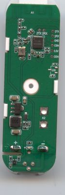
    Close-up of the PCB board of a single light switch with a CB3S module. .
    The switch is based on the CB3S module (similar to the WB3S):
    Electrical schematic and pinout of the CB3S module. .
    PCB designation: A-1011WL3B2-REV A0 2022-08-18
    Close-up view of the interior of a light switch with a CB3S module. .
    This large component in the SOIC is the touch button controller.
    A second PCB remains:
    Printed circuit board in the DS-101 light switch. .
    Designation of the second PCB: DS-101JL-3A-1 REV (A), 20221026.
    Light switch PCB with visible capacitors and relay. .
    Close-up of a PCB with a relay and capacitors. .
    On the board there is a small power supply in flyback topology and one relay. From underneath I can see additional electronics:
    PCB board of a switch with markings and electronic components. .
    Close-up of a PCB with electronic components, including the S7142S integrated circuit. .
    Close-up of a circuit board with electronic components. .
    Close-up of a PCB marked DS-101JL-3A-1 REV A0. .
    The power supply is based on the S7142S:
    Diagram of a switching power supply based on S7141S/S7142S chip. .
    What I don't know is why these NP3095s are there?
    Datasheet for NP3095G transistor.

    Firmware change 72-087 .
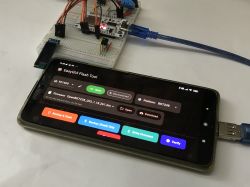
    You will need a USB to UART converter. According to the flasher instructions:
    https://github.com/openshwprojects/BK7231GUIFlashTool
    Or according to our YT video:


    .
    Soldered wires (see pinout CB3S):
    Light switch PCB with connected wires. .
    PCB with attached wires and light switch. .
    Flasher correctly reads GPIO configurations:
    Firmware flashing tool screen displaying JSON files for device configuration.
    JSON Tuya:
    Code: JSON
    Log in, to see the code

    OBK template:
    Code: JSON
    Log in, to see the code

    Import instructions:


    Instructions for pairing with HA:


    Copy of factory software:
    https://github.com/openshwprojects/FlashDumps/commit/0d2ae0b9796aaf6172a2d76beac313c8526a474c

    Summary .
    The switch has been correctly programmed and returned to the reader. Along with this switch I got a bit more hardware, which I'll put in separate topics, but I'll already announce what's going to be in them - there's a topic getting ready about a garage door controller and an external socket, this time on an ESP8266.
    The switch itself shown here turned out to be nothing new, essentially a repainted DS101, but from the outside I wasn't able to recognise it. In any case, freeing it from the manufacturer's cloud and connecting it to Home Assistant is seamless.

    Cool? Ranking DIY
    Helpful post? Buy me a coffee.
    About Author
    p.kaczmarek2
    Moderator Smart Home
    Offline 
    p.kaczmarek2 wrote 12478 posts with rating 10330, helped 586 times. Been with us since 2014 year.
  • ADVERTISEMENT
  • #2 21425161
    chemik_16
    Level 26  
    hah, I think you're following me ;D
    I have unbranded ones from Ali, at ~$7 for 4p and $5 for 2p, and was just about to go for them too.
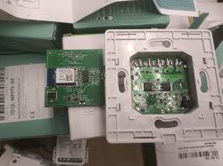
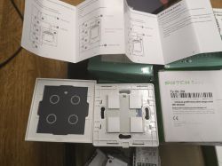
    Two electronic modules with visible circuit components and QR codes on a table. .
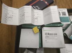
    Box with touch switch components and instruction manual. .
    User manual and boxes of smart switches on a table. .
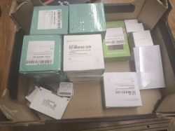
    Boxes of electronic components in a cardboard box. .

    differ in the front plate only because of the number of buttons
  • #3 21425165
    p.kaczmarek2
    Moderator Smart Home
    Show and see if it's the same as it was on mine. If you didn't pair it with Tuya, you can also share the original 2MB batch. Otherwise, Tuya's JSON alone (extracted by flasher) will suffice.
    Helpful post? Buy me a coffee.
  • #4 21425170
    chemik_16
    Level 26  
    >>21425165 .
    j.w.
    i have a whole carton of these, not used apart from 1 for testing.
    I will download them tomorrow.
  • #5 21425201
    p.kaczmarek2
    Moderator Smart Home
    Well, a substantial set. I look forward to seeing the results. Make a note of which dump and configuration from which device it is, these will come in handy to complete our list:
    https://openbekeniot.github.io/webapp/devicesList.html
    We'll probably hit 700 devices later this month (8 are missing).
    Helpful post? Buy me a coffee.
  • ADVERTISEMENT
  • #6 21427232
    chemik_16
    Level 26  
    here we go:
    101JL-WHITE-04
    CB3S
    readResult_BK7231N_QIO_2025-06-2-12-23-50.bin
    {
    	"rl1_lv":"1",
    	"netled_lv":"0",
    	"bt_type":"0",
    	"bt1_pin":"24",
    	"net_trig":"4",
    	"cd_flag2":"1",
    	"backlit_select":"1",
    	"nety_led":"0",
    	"backlit_io_pin":"23",
    	"netled_pin":"22",
    	"total_stat":"2",
    	"bt1_lv":"0",
    	"module":"CB3S",
    	"rl2_pin":"8",
    	"light_status_select":"0",
    	"cyc_dpid":"17",
    	"bt2_lv":"0",
    	"rl1_pin":"6",
    	"rl4_lv":"1",
    	"rl3_pin":"9",
    	"rl3_lv":"1",
    	"rand_dpid":"18",
    	"led_dp":"15",
    	"rl4_pin":"26",
    	"jv":"1.0.0",
    	"backlit_io_lv":"1",
    	"bt3_lv":"0",
    	"reset_t":"9",
    	"rl2_lv":"1",
    	"ch_flag1":"1",
    	"ch_flag3":"1",
    	"bt4_pin":"14",
    	"ch_flag4":"1",
    	"inch_dp":"19",
    	"bt3_pin":"7",
    	"ch_cddpid1":"7",
    	"init_conf":"14",
    	"bt4_lv":"0",
    	"bt2_pin":"20",
    	"ch_cddpid4":"10",
    	"ch_cddpid2":"8",
    	"ch_cddpid3":"9",
    	"backlit_dp":"16",
    	"ch_num":"4",
    	"ch_dpid3":"3",
    	"ch_dpid4":"4",
    	"netn_led":"1",
    	"ch_dpid1":"1",
    	"ch_dpid2":"2",
    	"crc":"40"
    }
    .
    Device configuration, as extracted from Tuya: 
    - Button (channel 1) on P24
    - Backlit IO pin on P23
    - WiFi LED on P22
    - Relay (channel 2) on P8
    - Relay (channel 1) on P6
    - Relay (channel 3) on P9
    - Relay (channel 4) on P26
    - Button (channel 4) on P14
    - Button (channel 3) on P7
    - Button (channel 2) on P20
    Device seems to be using CB3S module, which is using BK7231N.
    And the Tuya section starts, as usual, at 2023424
    
    .

    [/code].
  • #7 21427238
    p.kaczmarek2
    Moderator Smart Home
    JSON for the above file from 101JL-WHITE-04 readResult_BK7231N_QIO_2025-06-2-12-23-50.bin:
    Code: JSON
    Log in, to see the code
    .
    Verbal description:
    
    Device configuration, as extracted from Tuya: 
    - Button (channel 1) on P24
    - Backlit IO pin on P23
    - WiFi LED on P22
    - Relay (channel 2) on P8
    - Relay (channel 1) on P6
    - Relay (channel 3) on P9
    - Relay (channel 4) on P26
    - Button (channel 4) on P14
    - Button (channel 3) on P7
    - Button (channel 2) on P20
    Device seems to be using CB3S module, which is using BK7231N.
    And the Tuya section starts, as usual, at 2023424
    
    
    .
    I see that separately there is WiFiLED and backlight IO, not bad....

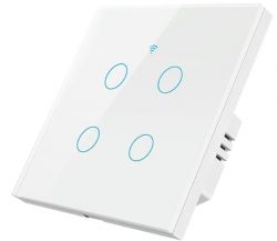
    Does the photo agree?
    White touch panel with four illuminated buttons and a WiFi icon on top.
    OBK template:
    Code: JSON
    Log in, to see the code
    .

    Added after 5 [minutes]:

    @chemik_16 if possible I would recommend checking if these switches have an RF receiver inside too? I've bought so many of these products that I know that even sometimes you get a surprise RF that isn't announced in the listing description. If it is, there will be a separate antenna (path) on the PCB and probably a circuit in SOIC8 with an additional quartz resonator.
    Helpful post? Buy me a coffee.
  • #9 21427251
    p.kaczmarek2
    Moderator Smart Home
    It's also a BK7231N core, you flash the same way. I think the newer Tuya devices on T34 are becoming more common.
    But fart, a T34 with pads derived?
    Also rip a 2MB batch and you can upload OBK.

    We've already had a T34 without derived pads:
    [BK7231N / T34] Teardown Tuya Generic Wifi Wall Switch 3-fold .
    Helpful post? Buy me a coffee.
  • #10 21427263
    chemik_16
    Level 26  
    attached, this is where the app failed to find json
    Failed to extract Tuya keys - no json start found
    Sorry, failed to extract keys from Tuya Config in backup binary.

    2 ICs obliterated, but one is the same as in all of them, from the buttons.
    the small one is flash or RF? probably RF
  • #11 21427275
    p.kaczmarek2
    Moderator Smart Home
    Flash tool is not yet perfect. I poked around on my side and got it:
    Code: JSON
    Log in, to see the code
    .
    
    Device seems to be using T34-3 module, which is BK7231T chip.
    - Relay (channel 1) on P9
    - Relay (channel 2) on P15
    - Relay (channel 3) on P17
    - WiFi LED on P7
    - Button (channel 1) on P16
    - Button (channel 2) on P14
    - Button (channel 3) on P8
    - Pair/Toggle All Pin on P24
    
    .

    OBK template:
    Code: JSON
    Log in, to see the code
    .

    Added after 0 [seconds]: .

    The small one in the SOIC8 is the RF. He is connected to the button controller with more legs. When you change the firmware of the WiFi/T34/BK7231 module, you still have RF working, because the WiFi module "doesn't know" about the circuit from RF.

    PS: Oddly, it also found: - Pair/Toggle All Pin on P24 - to check this is....
    Helpful post? Buy me a coffee.
  • #12 21427301
    chemik_16
    Level 26  
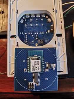
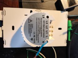
    Another one, 4p ala brazil, but it fits into EU cans (I'm about to give one that doesn't fit as well ;D)
    I do not have a box from it, but I will see on ali
    edit: https://pl.aliexpress.com/item/1005007420510766.html
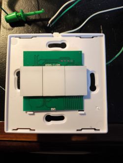
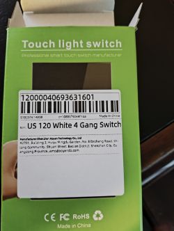
    Touch switch box with an informational label.

    Touch panel with a white casing and four buttons for wall mounting, showing interior electronics. .
    Electronic module with a blue PCB and components. .
    WiFi wall switch with visible L1, L2, L3, L4, and N terminals. .

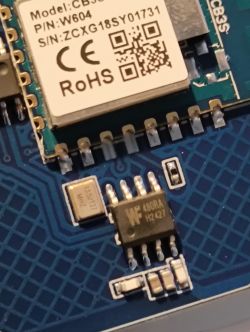
    these did not obliterate the RF, probably the same circuit
    they didn't clean too much after soldering ;D
    Close-up of a printed circuit board with a CB3S module and other electronic components. .
  • #13 21427310
    p.kaczmarek2
    Moderator Smart Home
    The WF480RA has already appeared on the forum https://www.elektroda.com/rtvforum/find.php?q=WF480RA
    I wouldn't worry about it though, here it is also connected to the button controller, so RF will continue to work after the firmware change. Show a copy of the 2MB batch.

    PS: What is the motivation for buying such a switch format? Do you want to use such, or is it as an experiment?
    Helpful post? Buy me a coffee.
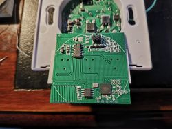
  • #14 21427312
    chemik_16
    Level 26  
    p.kaczmarek2 wrote:
    PS: What is the motivation for buying such a switch format? Do you want to use such, or is it as an experiment?
    .
    These Brazilian ones were the first 2 I bought, I didn't even know they were different from the rest :)

    @U.P. attached
  • #15 21427333
    p.kaczmarek2
    Moderator Smart Home
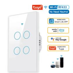
    Tuya smart touch panel with four buttons, supporting RF433, Alexa, Google Assistant, and other apps. .
    Tuya JSON:
    Code: JSON
    Log in, to see the code

    Verbal description:
    
    Device configuration, as extracted from Tuya: 
    - Button (channel 1) on P9
    - Backlit IO pin on P23
    - WiFi LED on P11
    - Relay (channel 2) on P24
    - Relay (channel 1) on P26
    - Relay (channel 3) on P14
    - Relay (channel 4) on P6
    - Button (channel 4) on P10
    - Button (channel 3) on P7
    - Button (channel 2) on P8
    Device seems to be using CB3S module, which is using BK7231N.
    And the Tuya section starts, as usual, at 2023424


    OBK:
    Code: JSON
    Log in, to see the code
    .

    With this number of additional buttons, it is easy either in the OBK itself or in the HA to make automations like "light switch (additional button) turns on LED strip from above the window", etc.
    Helpful post? Buy me a coffee.
  • ADVERTISEMENT
  • #16 21427337
    chemik_16
    Level 26  
    That was my goal ;) and these 4p and 1p cost the same after coin discounts. I'll stick some icons on the buttons or laser engrave them.

    Next, brasil


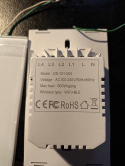
    Close-up of the back of a control panel model DS-1211AN with voltage and connectivity information. .
    Brazilian can, does not fit EU/US cans
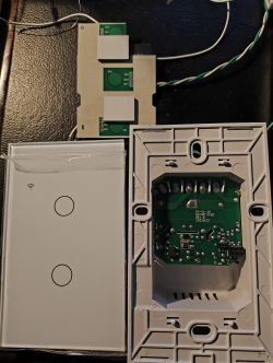
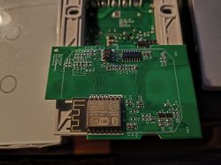
    Close-up of a green printed circuit board (PCB) with a WiFi module and electronic components. .
    Disassembled touch switch with circuit board and casing. .

    My first, pcb on rich ;) .
    common for 1-4P, can be extended

    variant with BT+wifi

    but its already BK does not move
    probably the one here
    https://www.elektroda.com/rtvforum/topic4086736.html
  • #17 21427357
    p.kaczmarek2
    Moderator Smart Home
    But is it BT alone or also with WiFi?
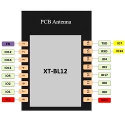
    XT-BL12 I see, which indicates BL602:
    Cozylife DS-1211AN 3Gang Touch Switch: 1MB BL602L10 [XT-BL12][DT-BL12] - Images, firmware ia .
    Worse, according to the information, it's a BL602 with 1MB Flash, so it would require a bit of playing around. Need to post in the linked topic (but on Elektroda.com), maybe @divadiow still has this switch and will take part in testing.

    You would need to disable unnecessary drivers in obk_config.h to reduce the size of the flash used....

    You can make a copy of the batch anyway, but that's with BLDevCube. We have a collection of flash tools here:
    https://github.com/openshwprojects/FlashTools
    Helpful post? Buy me a coffee.
  • #18 21427368
    chemik_16
    Level 26  
    well, i don't really care about the latter. i'll just solder esp8266 in there :D

    and that's it, i don't have any more switches, the rest is more 3p and 4p

    edit can't read it anyway
    Spoiler:
    [14:17:53.529] - Version: eflash_loader_v2.5.1
    [14:17:53.529] - Program Start
    [14:17:53.529] - ========= eflash loader cmd arguments =========

    [14:17:53.531] - serial port is COM4
    [14:17:53.531] - cpu_reset=False
    [14:17.53.532] - chiptype: bl602
    [14:17.53.534] - ========= interface is uart =========
    [14:17.53.534] - com speed: 2000000
    [14:17:53.534] - Eflash load helper file: C:\nEflash_loader/eflash_loader_40m.bin
    [14:17:53.535] - ========= load eflash_loader.bin =========
    [14:17:53.535] - Load eflash_loader.bin via uart
    [14:17:53.535] - ========= image load =========
    [14:17:53.803] - Not ack OK
    [14:17:53.803] - FL
    [14:17:53.804] - result: FL
    [14:17:54.094] - tx rx and power off, press the machine!
    [14:17:54.095] - cutoff time is 0.1
    [14:17:54.203] - power on tx and rx
    [14:17:55.021] - reset cnt: 0, reset hold: 0.005, shake hand delay: 0.1
    [14:17:55.023] - clean buf
    [14:17.55.051] - send sync
    [14:17:55.160] - ack is
    [14:17.55.160] - retry
    [14:17:55.424] - tx rx and power off, press the machine!
    [14:17:55.425] - cutoff time is 0.1
    [14:17:55.531] - power on tx and rx
    [14:17:56.339] - reset cnt: 0, reset hold: 0.005, shake hand delay: 0.1
    [14:17:56.339] - clean buf
    [14:17:56.371] - send sync
    [14:17:56.478] - ack is
    [14:17:56.478] - retry
    [14:17:56.493] - shake hand fail
    [14:17:56.493] - ########################################################################
    [14:17:56.494] - 请按照以下描述排查问题:
    [14:17:56.495] - GPIO8是否上拉到板子自身的3.3V,而不是外部的3.3V
    [14:17:56.495] - GPIO7(RX)是否连接到USB转串口的TX引脚
    [14:17:56.495] - GPIO16(TX)是否连接到USB转串口的RX引脚
    [14:17:56.495] - 在使用烧录软件进行烧录前,是否在GPIO8拉高的情况下,使用Reset/Chip_En复位了芯片
    [14:17:56.497] - 烧录软件所选择的COM口,是否是连接芯片的串口
    [14:17:56.497] - 烧录软件上选择的波特率是否是USB转串口支持的波特率
    [14:17:56.497] - 3.3V供电是否正常
    [14:17:56.497] - 板子供电电流是否正常(烧录模式下,芯片耗电电流5-7mA)
    [14:17:56.497] - ########################################################################
    [14:17:56.497] - shake hand fail
    [14:17:56.502] - Load helper bin time cost(ms): 2967.82080078125
    [14:17:56.505] - ErrorCode: 0003, ErrorMsg: BFLB LOAD HELP BIN FAIL
    [14:17:56.505] - Burn Retry
    [14:17:56.505] - 0
    [14:17:56.505] - Burn return with retry fail
    [14:17:56.505] - ========= flash read jedec ID =========
    [14:17:56.507] - Flash load shake hand
    [14:17:56.546] - default set DTR high
    [14:17.56.649] - clean buf
    [14:17:56.679] - send sync
    [14:17:56.787] - ack is
    [14:17:56.787] - retry
    [14:17:56.788] - default set DTR high
    [14:17:56.896] - clean buffer
    [14:17:56.926] - send sync
    [14:17:57.038] - ack is
    [14:17:57.038] - retry
    [14:17:57.054] - ErrorCode: 0001, ErrorMsg: BFLB EFLASH LOADER SHAKEHAND FAIL
    [14:17:59.922] - Version: eflash_loader_v2.5.1
    [14:17:59.922] - Program Start
    [14:17:59.922] - ========= eflash loader cmd arguments =========

    [14:17:59.924] - serial port is COM4
    [14:17:59.925] - cpu_reset=False
    [14:17:59.925] - chiptype: bl602
    [14:17:59.925] - ========= interface is uart =========
    [14:17:59.925] - com speed: 2000000
    [14:17:59.926] - Eflash load helper file: C:C:Users.orgBouffaloLabDevCube-v1.9.0.0chipsbl602eflash_loader/eflash_loader_40m.bin
    [14:17:59.926] - ========= load eflash_loader.bin =========
    [14:17:59.926] - Load eflash_loader.bin via uart
    [14:17:59.926] - ========= image load =========
    [14:18:00.178] - Not ack OK
    [14:18:00.178] - FL
    [14:18:00.178] - result: FL
    [14:18:00.474] - tx rx and power off, press the machine!
    [14:18:00.475] - cutoff time is 0.1
    [14:18:00.581] - power on tx and rx
    [14:18:01.398] - reset cnt: 0, reset hold: 0.005, shake hand delay: 0.1
    [14:18:01.398] - clean buf
    [14:18:01.428] - send sync
    [14:18:01.538] - ack is
    [14:18:01.538] - retry
    [14:18:01.803] - tx rx and power off, press the machine!
    [14:18:01.804] - cutoff time is 0.1
    [14:18:01.911] - power on tx and rx
    [14:18:02.718] - reset cnt: 0, reset hold: 0.005, shake hand delay: 0.1
    [14:18:02.718] - clean buffer
    [14:18:02.748] - send sync
    [14:18:02.856] - ack is
    [14:18:02.856] - retry
    [14:18:02.871] - shake hand fail
    [14:18:02.872] - ########################################################################
    [14:18:02.872] - 请按照以下描述排查问题:
    [14:18:02.873] - GPIO8是否上拉到板子自身的3.3V,而不是外部的3.3V
    [14:18:02.874] - GPIO7(RX)是否连接到USB转串口的TX引脚
    [14:18:02.874] - GPIO16(TX)是否连接到USB转串口的RX引脚
    [14:18:02.874] - 在使用烧录软件进行烧录前,是否在GPIO8拉高的情况下,使用Reset/Chip_En复位了芯片
    [14:18:02.875] - 烧录软件所选择的COM口,是否是连接芯片的串口
    [14:18:02.875] - 烧录软件上选择的波特率是否是USB转串口支持的波特率
    [14:18:02.875] - 3.3V供电是否正常
    [14:18:02.875] - 板子供电电流是否正常(烧录模式下,芯片耗电电流5-7mA)
    [14:18:02.875] - ########################################################################
    [14:18:02.875] - shake hand fail
    [14:18:02.878] - Load helper bin time cost(ms): 2951.8623046875
    [14:18:02.880] - ErrorCode: 0003, ErrorMsg: BFLB LOAD HELP BIN FAIL
    [14:18:02.882] - Burn Retry
    [14:18:02.885] - 0
    [14:18:02.887] - Burn return with retry fail
    [14:18:02.890] - ========= flash read jedec ID =========
    [14:18:02.892] - Flash load shake hand
    [14:18:02.935] - default set DTR high
    [14:18:03.046] - clean buf
    [14:18:03.075] - send sync
    [14:18:03.187] - ack is
    [14:18:03.187] - retry
    [14:18:03.188] - default set DTR high
    [14:18:03.295] - clean buffer
    [14:18:03.325] - send sync
    [14:18:03.434] - ack is
    [14:18:03.434] - retry
    [14:18:03.448] - ErrorCode: 0001, ErrorMsg: BFLB EFLASH LOADER SHAKEHAND FAIL
    .
  • ADVERTISEMENT
  • #19 21427414
    p.kaczmarek2
    Moderator Smart Home
    Helpful post? Buy me a coffee.
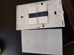
  • #20 21428051
    chemik_16
    Level 26  
    btw, all of the above worked without the neutral wire, and I had a capacitor included in each too. Yours probably did too, as it's the same base.
    I.e. they worked is a slight overinterpretation, they would have worked if I didn't have the leds :) yes these bulbs flicker for the first few minutes after switching on.
    These I have already bought for a new house where I have N at every switch.
  • #21 21434133
    p.kaczmarek2
    Moderator Smart Home
    As far as I can see they have launched the BL602 on a chip with 1MB Flash:
    https://www.elektroda.com/rtvforum/topic4086736.html#21434069
    Have you tried reading the flash from what you have? Or have you already soldered it out?
    Helpful post? Buy me a coffee.
  • #22 21434149
    chemik_16
    Level 26  
    No, I haven't done anything further with it. I can't get mine to read/write, I don't know which pin is boot, I don't see anything like that in the documentation.
    I even cut the rx tx paths because they are used for something, but no change.
  • #23 21434154
    p.kaczmarek2
    Moderator Smart Home
    Helpful post? Buy me a coffee.
  • #24 21434156
    chemik_16
    Level 26  
    should be connected to GND or 3v3?
    I understand that it is enough to disconnect the power supply ?
  • #25 21434181
    p.kaczmarek2
    Moderator Smart Home
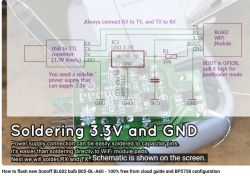
    As far as I can see, on these BL602s the boot needs to be at a high level to enable the bootloader from the UART. That is, up to 3.3V.
    I remember connecting it with a 10k resistor to the power supply. [EDIT] Now I don't know if this resistor can be omitted, better not.


    .

    Schematic of soldering 3.3V and GND on a board with BL602 WiFi module. .


    First try reading the flash.
    Helpful post? Buy me a coffee.
  • #26 21434649
    chemik_16
    Level 26  
    nope, doesn't go anywhere. when i pull up 8 to 3v3 it just goes off led, it was pulled up by 8kom to ground.
    In the connection it continues the same, even the chip id can't be read.

    edit. now it seems to have died at all, only the bottom button lights up red, buttons don't work, no wifi flashes

    edit, oh it works.
    You have to connect the 3v3 to the io8, reset and disconnect. All in all, I don't know how to get out of this mode afterwards, because unplugging it doesn't reset it ;D
    [12:02:29.720] - serial port is COM4
    [12:02:29.720] - cpu_reset=False
    [12:02:29.720] - chiptype: bl602
    [12:02:29.720] - ========= Interface is uart =========
    [12:02:29.721] - com speed: 20000
    [12:02:29.721] - Eflash load helper file: C:\Users\kenavru\Documents\BouffaloLabDevCube-v1.9.0\chips\bl602\eflash_loader/eflash_loader_40m.bin
    [12:02:29.721] - ========= load eflash_loader.bin =========
    [12:02:29.721] - Load eflash_loader.bin via uart
    [12:02:29.721] - ========= image load =========
    [12:02:29.984] - Not ack OK
    [12:02:29.984] - FL
    [12:02:29.985] - result: FL
    [12:02:30.278] - tx rx and power off, press the machine!
    [12:02:30.279] - cutoff time is 0.1
    [12:02:30.387] - power on tx and rx
    [12:02:31.195] - reset cnt: 0, reset hold: 0.005, shake hand delay: 0.1
    [12:02:31.195] - clean buf
    [12:02:31.230] - send sync
    [12:02:31.444] - ack is 4f4b
    [12:02:31.506] - shake hand success
    [12:02:31.521] - get_boot_info
    [12:02:31.523] - data read is b'0100000000000000030004002d21abcf0eb41800'
    [12:02:31.524] - ========= chipid: b40ecfab212d =========
    [12:02:31.524] - last boot info: None
    [12:02:31.524] - sign is 0 encrypt is 0
    [12:02:31.525] - segcnt is 1
    [12:02:31.531] - segdata_len is 38592
    [12:02:31.615] - 4080/38592
    [12:02:31.699] - 8160/38592
    [12:02:31.781] - 12240/38592
    [12:02:31.864] - 16320/38592
    [12:02:31.949] - 20400/38592
    [12:02:32.031] - 24480/38592
    [12:02:32.115] - 28560/38592
    [12:02:32.197] - 32640/38592
    [12:02:32.281] - 36720/38592
    [12:02:32.320] - 38592/38592
    [12:02:32.321] - Run img
    [12:02:32.431] - Load helper bin time cost(ms): 2710.052490234375
    [12:02:32.540] - Flash load shake hand
    [12:02:32.582] - default set DTR high
    [12:02:32.696] - clean buf
    [12:02:32.729] - send sync
    [12:02:32.946] - ack is 4f4b
    [12:02:33.007] - Read mac addr
    [12:02:33.021] - macaddr: 2d21abcf0eb4
    [12:02:33.022] - flash set para
    [12:02:33.022] - ========= flash read jedec ID =========
    [12:02:33.033] - Read flash jedec ID
    [12:02:33.034] - flash jedec id: c2201480
    [12:02:33.035] - Finished
    [12:02:33.042] - get flash size: 0x00100000
    [12:02:33.042] - ========= flash read jedec ID =========
    [12:02:33.053] - Read flash jedec ID
    [12:02:33.053] - flash jedec id: c2201480
    [12:02:33.054] - Finished


    but I can't read it, I set start 0x00 end 0x00100000
    [12:04:05.776] - ========= chipid: b40ecfab212d =========
    [12:04:05.776] - last boot info: None
    [12:04:05.776] - eflash loader present
    [12:04:05.776] - Error: Image load fail
    [12:04:05.777] - shakehand with eflash loader found
    [12:04:05.777] - Load helper bin time cost(ms): 1822.815185546875
    [12:04:05.777] - ErrorCode: 0003, ErrorMsg: BFLB LOAD HELP BIN FAIL
    [12:04:05.777] - Burn Retry
    [12:04:05.777] - 0
    [12:04:05.777] - Burn return with retry fail
    .

    Added after 38 [minutes]:

    what a wild monster this 602 is, you have to do a reset after every operation.
    flash end I set 0xfffff
    0x100000 gets overflow ...

    reads itself, slowly because slowly ...
    in the attachment, but I don't know if the whole thing, because only up to 0xfffff, but he is mostly empty anyway.
    [12:30:22.623] - ========= flash read jedec ID =========
    [12:30:22.626] - Read flash jedec ID
    [12:30:22.626] - flash jedec id: c2201480
    [12:30:22.626] - Finished
    [12:30:22.631] - get flash size: 0x00100000
    [12:30:22.632] - Read operation
    [12:30:22.632] - read flash end addr 0x00100000 was overflow with flash size 0x00100000
    [12:30:22.632] - ErrorCode: 0045, ErrorMsg: BFLB FLASH SIZE OVER FLOW
    .

    is there any version of what i can upload there ? from that thread ?
  • #27 21434914
    p.kaczmarek2
    Moderator Smart Home
    I've encountered this flash reading, and I remember that I think I typed 1 megabyte there without a single byte (or 2 megabytes there, because I had 2MB).

    In the linked topic I think @divadiow fired it up somehow, I think even just selecting a different TOML partition map? I don't know, I haven't followed it that much. You can log on to elektroda com and ask there in English. This initiative with changing the firmware of various products on Elektroda is already so big that I'm not personally involved in every operation, users work too.

    chemik_16 wrote:
    .
    what a wild monster this 602 is, after every operation you have to do a reset.

    Reset or power off/on? On the ESP8266 when I short-circuit GPIO0 to ground to enter UART bootloader mode I also have to cut and reconnect power after one operation with esptool, from what I remember.
    Helpful post? Buy me a coffee.
  • #28 21434970
    chemik_16
    Level 26  
    p.kaczmarek2 wrote:
    Reset or power off/on? On the ESP8266 when I short-circuit GPIO0 to ground to enter UART bootloader mode I also have to cut and reconnect power after one operation with esptool, from what I remember.
    .

    Here I once shorted 3v3 to IO8, on/off.
    Since then I can perform 1 operation e.g.: checkID, read.
    on/off
    another operation.

    The bl602 is all the time in boot mode, the switch software doesn't start, I don't know how to get out of it, short to ground ? ;D

    but I downloaded it, the binary looks reasonable. All in all these Chinese programs are always full of errors, maybe they count from 0x01 :D or end +1
  • #29 21437316
    p.kaczmarek2
    Moderator Smart Home
    Many BL602 pieces it was I didn't have, but I'm sure that after unplugging the boot pin and doing a power off/on cycle already everything was back to normal. Type yourself a BL602 on our channel:
    https://www.youtube.com/@elektrodacom

    Or maybe you have uploaded something wrong and that is causing the bootloop?
    Helpful post? Buy me a coffee.
  • #30 21438633
    p.kaczmarek2
    Moderator Smart Home
    Helpful post? Buy me a coffee.
📢 Listen (AI):

Topic summary

The discussion centers on single and multi-gang WiFi light switches compatible with Home Assistant after firmware modification, focusing on models under vendor code 72-087 and related designations such as DS-101, DS-111, DS-151, DS-161, DS-1011ZC, and CB3S. Firmware flashing is performed via UART, enabling 100% local control. Participants share experiences with unbranded AliExpress switches and Brazilian variants, noting differences in form factor and compatibility with EU wall boxes. The switches typically include a capacitor to enable operation without a neutral wire, though LED flickering issues are reported. The core chips discussed are BK7231N and BL602, with the latter presenting challenges due to its 1MB flash size and boot mode pin configuration (IO8). Flashing tools and JSON configuration dumps are exchanged to facilitate integration with OpenBeken firmware. The conversation also touches on relay versus triac-based switching mechanisms, noise issues related to relay cycling, and scripting capabilities in OpenBeken for automatic relay turn-off after a set time. Some users report difficulties reading/writing flash on BL602 devices and share troubleshooting steps involving boot pin manipulation and power cycling. The community references resources such as the OpenBeken device list and GitHub repositories for flash tools and firmware. Overall, the thread provides detailed technical insights into firmware modification, hardware compatibility, and integration of low-cost WiFi switches with Home Assistant using open-source firmware.
Summary generated by the language model.
ADVERTISEMENT