logo elektroda
logo elektroda
X
logo elektroda

How to Open and Disassemble Gerier 1CH WiFi Switch LED 250W 10A Safely

DreamWarrior2412 966 7
ADVERTISEMENT
  • #1 20993516
    DreamWarrior2412
    Level 3  
    This switch is the 1CH variant of the Gerier WiFi Switch series. It is really a small device...
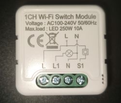
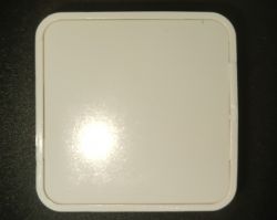
    Back of 1-channel WiFi switch module with specification label and wiring screws. Rectangular device with a white casing on a black background.

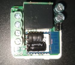
    Start the teardown by turning the device so that you have the back on top. Use a small knife to open it from any side. Just in the middle of each side you can push a small knife in and open the case without destroying it. After opening the case backside take of the PCB by pressing on the green wire screwbar.
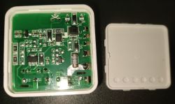
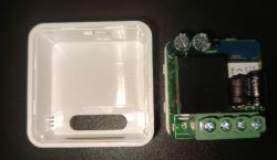
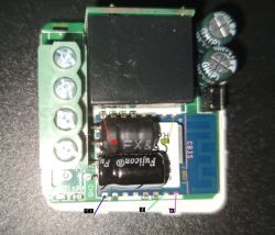
    Image of an open 1-channel Gerier WiFi switch showing the circuit board. Opened device showing plastic casing and circuit board with electronic components. Interior of Gerier WiFi switch with visible CB3S module and electronic components.

    The device uses the CB3S Module. I used this time a 3D Printed PogoPin Adapter I've got aware of in a YouTube Video ( https://www.thingiverse.com/thing:4099748 PogoPins from Amazon https://www.amazon.de/dp/B007Q8JILQ ). After connecting everything necessary for flashing, just start the usual procedure.
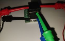
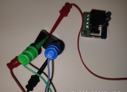
    Close-up of a 1-channel Gerier WiFi switch with connected test leads. Connected circuit board with colored wires and PogoPin adapter.

    Configuration according to what being read from the original software image. Please set PowerSave 1 Option in OpenBeken autoexec.bat .
    
    {
      "vendor": "Gerier",
      "bDetailed": "0",
      "name": "1CH WiFi Switch",
      "model": "LED 250W 10A",
      "chip": "BK7231N",
      "board": "CB3S",
      "flags": "1024",
      "keywords": [
        "relay",
        "module",
        "ZH-Z01 REV:C"
      ],
      "pins": {
        "6": "Rel;1",
        "8": "TglChanOnTgl;1",
        "9": "WifiLED_n;0",
        "26": "Btn_Tgl_All;0"
      },
      "command": "",
      "image": "https://obrazki.elektroda.pl/5962629300_1709760458.jpg",
      "wiki": "https://www.elektroda.com/rtvforum/topic4040929.html"
    }
  • ADVERTISEMENT
  • #2 20999272
    io2345
    Level 8  
    Thank you for the guide.
    Could you eventually provide a photo that shows where to connect Pins? RX, TX, V+ and GND as usual.
    Thank you.
  • ADVERTISEMENT
  • #3 20999285
    DreamWarrior2412
    Level 3  
    Actually this is shown in 1st picture last row. I've used the PogoPin adapter by pressing it on the Module...

    So if you ask for the PINs I used

    3=Reset connect it to GND on PIN 9 for short moment to start reading/writing when Programming App asks you to do.
    8=3V->3V on USB Adapter
    9=GND->GND on USB Adapter
    15=RX->TX on USB Adapter
    16=TX->RX on USB Adapter

    So you see - I even didn't solder at all ;-)
  • ADVERTISEMENT
  • #4 20999351
    io2345
    Level 8  
    Thanks for your fast reply. I'm still Beginner level, but I prefer to solder in order to get stable connections.
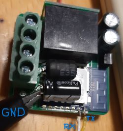
    So Pins should be those on the attached photo
    A circuit board with visible pins labeled as GND, RX, TX, CEN, and capacitors.
    It will be my first flash of those IoT stuff. Is there a small but good Beginners guide available somewhere? Is any USB-FlashDevice suitable? I still have here a CH340G (used for ESP01-programming). Probably good enough for that (?)
  • #5 20999373
    DreamWarrior2412
    Level 3  

    Well - compared to others I would say I'm on a flashing beginner level, too ;-)
    The pins you've marked are the ones I used. I actually didn't want to solder because of 3.3v and Reset are both at places where there is too much risk to heat up everything else and to melt the plastic from the relay...

    The CH340G is actually that what I use to flash my devices to OpenBeken.

    Careful - Reset by Power Off means in my case that the device is fully reconnected and com connection gets lost so you have to use the Pin3 RESET to Pin8 GND Method. And keep in mind - you just have a short moment and just need a short shortening moment.
  • #6 20999403
    io2345
    Level 8  
    Alright. So I'll solder the lower three contacts and contact the inner ones solderless by just pressing on them.
    Keep fingers crossed ;-)
  • ADVERTISEMENT
  • #7 21088115
    io2345
    Level 8  
    DreamWarrior2412 wrote:
    PowerSave 1 Option

    How do I set that in autoexec.bat?

    Another question: Under which name can I find this device in the devices list with 573 entries? Even with filtering for BK7231N there are still 284 devices.

    Hinzugefügt nach 6 [Stunden] 15 [Minuten]:

    A hint for making it a little easier to flash:
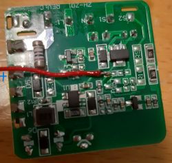
    Just solder TX and RX on the upside of the board and V+ (3,3V) on the other side (see photos). Use the outer pin of the big capacitor on the upside as ground pin:
    Close-up of a circuit board with marked TX, RX, and GND points. Image of a green circuit board with electronic components and a red wire soldered to one of the points on the board.

    Hinzugefügt nach 12 [Minuten]:

    If you are on ioBroker, you'll have to create the "set" value manually (as always):
    In MQTT-Tree under <device name>, 1, you'll find the "get" value. Under 1 you create now manually a new entry as "state", type "number" and name "set". Now make a right click on "set" to edit, change the role to "variable".
    ioBroker interface showing get and set values as variables in a folder.
  • #8 21091899
    DreamWarrior2412
    Level 3  
    io2345 wrote:
    How do I set that in autoexec.bat?


    Please open the device web interface in your browser. Click on "Launch web application", select "Filesystem" tab. Now - either click on "Create File" and type filename "autoexec.bat" or "List Filesystem" and select "autoexec.bat". Paste the command in file, save file and reboot device.

    When opening the web page of device again you will find, after open the web application again and select the logs tab lines like this in the log window:

    Info:MAIN:Time 3778374, idle 75296/s, free 69112, MQTT 1(520), bWifi 1, secondsWithNoPing -1, socks 2/38 POWERSAVE

    Seems that device didn't find its way into the database.. Actually find all settings in this thread the PINs are the relevant settings...


    Check for POWERSAVE. This means you successfully set the option in autoexec.bat

Topic summary

The discussion focuses on the safe disassembly and flashing of the Gerier 1CH WiFi Switch, detailing the process of opening the device, accessing the PCB, and connecting to the CB3S module using a PogoPin adapter. Users share specific pin connections for programming, emphasizing the importance of avoiding soldering to prevent damage. A beginner's guide to flashing IoT devices is requested, with recommendations for suitable USB flash devices like the CH340G. Additional tips include soldering specific pins for easier access and creating an autoexec.bat file for device configuration.
Summary generated by the language model.
ADVERTISEMENT