NAS-IR02W6 Pro V3
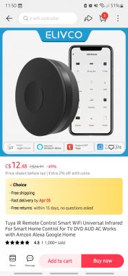
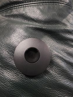
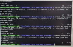
Hi! I have bought a cheap TuYa Wi-Fi IR emitter device from AliExpress for $5 CAD. I did not even bother adding it to smartlife app, I backed up and flashed it straight away. The pads/pins are very small, took a few tries to get things soldered up properly. The only issues with flashing or backing up were: not being able to figure out what pins are what from the tuya config section (but JSON output seems to have proper pin cfg?) and I had to set UART timeouts to 10, 10, 5. I use linux so this is all running using mono.
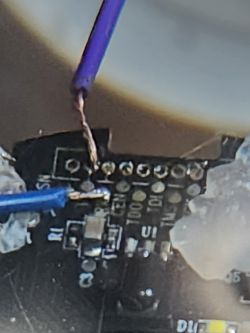
I connected TX, RX and GND to USB TTL and powered it using the USB-C port, I only needed to power cycle using USB cable to get it into read/write mode. Here is a picture of the TX/RX soldered up on the PCB:
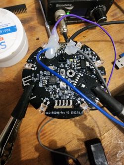
I saw a few other threads with these devices in earlier versions. From what I could tell, the posts say that the pin config is:
6 - Btn - ??? I used GPIO finder and I needed to set output low and input with no pull up. It starts low and on button press switches to high. It stays high and does not reset to low on release. How should I configure this?
8 - IRRecv - Correct
9 - WifiLED - Correct
26 - IRSend - Incorrect: for the Pro V3, the IRSend pin is 7
So, My only issue as of now is trying to configure the button on pin 6. In the below JSON, it is the reset_pin. If I set it as 'Btn' channel: 0, I get no presses logged. 'Btn_n' channel: 0, causes Button_OnLongPressHold in logs. I can't figure out how to get button presses recognized. I am restarting the device when changing pinouts.
In GPIO Finder, if I set pin 6 to dInput_NoPullUp and have the output set LOW, it only records the 1 button press and never sets itself back low. IDK how to configure this so the button toggles the output. Do I need to configure a channel? I am unsure of what channel means in this context, as this button doesn't control a relay AFAIK.
JSON code from reading original firmware:


Hi! I have bought a cheap TuYa Wi-Fi IR emitter device from AliExpress for $5 CAD. I did not even bother adding it to smartlife app, I backed up and flashed it straight away. The pads/pins are very small, took a few tries to get things soldered up properly. The only issues with flashing or backing up were: not being able to figure out what pins are what from the tuya config section (but JSON output seems to have proper pin cfg?) and I had to set UART timeouts to 10, 10, 5. I use linux so this is all running using mono.
I connected TX, RX and GND to USB TTL and powered it using the USB-C port, I only needed to power cycle using USB cable to get it into read/write mode. Here is a picture of the TX/RX soldered up on the PCB:


I saw a few other threads with these devices in earlier versions. From what I could tell, the posts say that the pin config is:
6 - Btn - ??? I used GPIO finder and I needed to set output low and input with no pull up. It starts low and on button press switches to high. It stays high and does not reset to low on release. How should I configure this?
8 - IRRecv - Correct
9 - WifiLED - Correct
26 - IRSend - Incorrect: for the Pro V3, the IRSend pin is 7
So, My only issue as of now is trying to configure the button on pin 6. In the below JSON, it is the reset_pin. If I set it as 'Btn' channel: 0, I get no presses logged. 'Btn_n' channel: 0, causes Button_OnLongPressHold in logs. I can't figure out how to get button presses recognized. I am restarting the device when changing pinouts.
In GPIO Finder, if I set pin 6 to dInput_NoPullUp and have the output set LOW, it only records the 1 button press and never sets itself back low. IDK how to configure this so the button toggles the output. Do I need to configure a channel? I am unsure of what channel means in this context, as this button doesn't control a relay AFAIK.
JSON code from reading original firmware:
Code: JSON


