logo elektroda
logo elektroda
X
logo elektroda

Flashing Currysmarter Gen6 Courtain Switch with OpenBeken: Disabling CMS79FT738 MCU while flashing

DreamWarrior2412 1791 10
ADVERTISEMENT
  • #1 20999183
    DreamWarrior2412
    Level 3  

    Hi all out there,

    I'd like to flash my Currysmart Gen6 Curtain switch with OpenBeken - but got stuck at the point on how to disable the MCU used on this board. Well yes, I could simply disconnect the TX/RX connections but this is actually what I want to avoid. In Tasmota Wiki they say this could be done by connecting RST/NRST to GND. The latter is easy for me to find ;-) The RST/NRST is the problem. Within available documentation there is no signal line with exactly this naming.

    That's why I decided to ask here for help. Documentation is available here - chip is CMS79FT738:

    https://www.mcu.com.cn/uploads/img1/tupian//%...8B%E8%BD%BD/CMS79F73x_User_Manual_V1.7%20.pdf

    If the only option left is to interrupt the TX/RX... OK, so I hope to find some help here. Afterwards I will post the teardown and all info that I have got from the device into the proper section here to help others to do the job an easy and quick way.

    Thanks for your help in advance

    Andreas
  • ADVERTISEMENT
  • #2 20999199
    p.kaczmarek2
    Moderator Smart Home
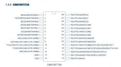
    Here is the pinout of your MCU:
    Diagram of the CMS79FT738 microcontroller pinout, showing pin layout and labels.
    I have skimmed both the pinout and the GPIO list at the page 13 and I can't see any RESET pin there. You may just need to use the soldering method. Do you know how to desolder the SOIC chip? It may be sometimes easier than cutting the traces.
    Helpful post? Buy me a coffee.
  • #3 20999215
    DreamWarrior2412
    Level 3  

    Thanks for your reply,

    well - regarding soldering I'm not a really specialist. I did learn it in school approx. 30 years ago... Since the PCB of the switch is quite thin compared to other PCBs that I've had in my hands before, I don't want to solder a lot on it because it may destroy more than it would help... And since I have not only one switch to update it would be great to ease this process as much as possible. So shorten some PINs would be best ;-)

    Did you find the ways on how to do a reset in documentation? They say something about undervoltage in the manual. The PCB has 4 unsoldered connection points close to the MCU labeled 3V3, GND, DAT, CLK on one side and on other side Update MCU. To Update/Flash the MCU, actually I would guess the MCU boot process maybe needs to be suspended, too - or the update process is part of the default program of the MCU on other hand...

    Andreas
  • ADVERTISEMENT
  • #4 20999328
    p.kaczmarek2
    Moderator Smart Home
    Undervoltage is not the solution there. Undervoltage happens when the VDD drops way below 3.3V and on your board 3.3V is most likely common for both WiFi module and the MCU. So that would affect both MCU and the BK.

    I haven't found indeed any RST/NRST/RESET pins in that datasheet. The listed RESET methods do not include a RESET pin. I think you may need to try the soldering approach.

    What kind of soldering equipment do you have?

    How the device board looks like?

    Do you feel more comfortable desoldering the MCU itself or do you prefer to cut and reconstruct the traces?
    Helpful post? Buy me a coffee.
  • #5 20999407
    DreamWarrior2412
    Level 3  

    p.kaczmarek2 wrote:
    Undervoltage is not the solution there. Undervoltage happens when the VDD drops way below 3.3V and on your board 3.3V is most likely common for both WiFi module and the MCU. So that would affect both MCU and the BK.


    OK. For sure you're right with this...

    p.kaczmarek2 wrote:
    I haven't found indeed any RST/NRST/RESET pins in that datasheet. The listed RESET methods do not include a RESET pin. I think you may need to try the soldering approach.


    Yeap... Well - will leave this open until the next few days. Maybe someone else has somehow by chance more experience with exactly this MCU...

    p.kaczmarek2 wrote:
    What kind of soldering equipment do you have?


    Some "cheap" Weller Digital Station... Model 1010

    p.kaczmarek2 wrote:
    How the device board looks like?


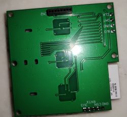
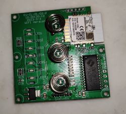
    Hey - OK... Well... Wanted to disclose it in Teardown ;-) Have a look at this here:
    Close-up of a green PCB with marked traces, CN2 port, and labels CLK, DAT, GND, and RX/TX. PCB with electronic components including a Wi-Fi module.
    These is the upper part. It connects via CN2 to a secondary PCB where the relays are located.

    p.kaczmarek2 wrote:
    Do you feel more comfortable desoldering the MCU itself or do you prefer to cut and reconstruct the traces?


    I think more about the option to cut the PCB lanes to interrupt TX/RX communication...

    Andreas
  • #6 20999418
    p.kaczmarek2
    Moderator Smart Home
    Ok so if you don't want to reconstruct traces then what about it.
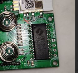
    1. Find with multimeter where TX and RX leads on the SOIC chip
    2. cut here:
    Close-up of a circuit board with highlighted soldering paths.
    3. instead of simply reconstructing the traces, solder wires to RX and TX of CBU and route them directly to the SOIC chip pins. This may be easier than reconstructing traces because those SOIC pins are larger than the tiny traces.
    Or wait, let's ignore that, you know what?
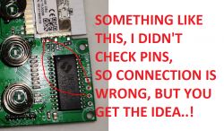
    You said yourself that you have RX/TX header of the MCU on the board. Doesn't it lead to the same RX/TX we speak about?
    If it leads, then you can just do jumpers there:
    Photo of a circuit board with red text annotations suggesting example connections.

    Added after 30 [seconds]:

    but I will repeat - I didn't check the pinouts on my image, it's just an example, it doesn't show correct connections.
    Helpful post? Buy me a coffee.
  • ADVERTISEMENT
  • #7 20999956
    DreamWarrior2412
    Level 3  

    p.kaczmarek2 wrote:
    You said yourself that you have RX/TX header of the MCU on the board. Doesn't it lead to the same RX/TX we speak about?
    If it leads, then you can just do jumpers there:


    Unfortunately this will not work out I think. I've measured where TX and RX of the CBU ends on the MCU - to keep it short and sweet... At the wrong PINs I would say since the CLK/DAT Pinouts connect to different PINs.

    To be precise PIN9 and PIN10 on MCU connect to the TX/RX of the CBU - but well... What about either disconnect the MCU TX->RX wire on PCB by scalpel and after flashing reconnect it by a little bit soldering "dot". Else option would be to disable power supply at the MCU... What about desoldering the 3V input so that the whole MCU is without Power? The 3V seems to be easier to reach and desolder (PIN 14 that is directly at the Edge of the MCU). I could either desolder this PIN or directly cut it and after flashing the CBU reconnect it.

    Other idea is to connect the CLK Pin to GND Pin. Should actually mean a short-circuited CLK = the MCU will maybe not work under these circumstances...
  • ADVERTISEMENT
  • #8 21000465
    p.kaczmarek2
    Moderator Smart Home
    Are you referring to ICSPCLK? It's just a CLK for programming signal, not the main device clock. I don't think it will affect the device functionality in any way.
    Helpful post? Buy me a coffee.
  • #9 21022910
    DreamWarrior2412
    Level 3  

    OK.. Little update on process...

    I've successfully after some little massacre managed to flash the CBU Module of the Currysmarter Gen6 switch. I tried first by cutting the 3V power supply of the MCU - unsuccessful. Afterwards I cut the TX and RX at the MCU. After soldering all wires for flashing I was able to fix the cutten legs of the chip by hard wiring them to the CBU Module TX and RX.

    For the next switches - since it seems impossible without soldering and even the available 3D Print Pogo adapters are too unprecise I will desolder the CBU Module by watching your video on YouTube and hopefully good luck in desoldering and soldering ;-)

    Actually I still found out already some functions of the MCU but seems that I need some Channel Type for the ENUM (0=Open, 1=Stop, 3=Close) for the Curtain style switch. I currently use the TextValue and set the enum value manually. Would be an idea to have such buttons free configurable regarding enum Value, Text and maybe position so that you could select them via a combo box in web interface... So actually there are more things that the switch can do. I will try to debug the MCU Communication using one of the original switches I still have to update...

    Andreas
  • #10 21262883
    mircofreiberg
    Level 2  
    Hi, did you find the right configuration so the Tuya CBU can process and control correctly?

    Added after 33 [seconds]:

    >>20999183 Hi, did you find the right configuration so the Tuya CBU can process and control correctly?

    Added after 23 [minutes]:

    >>20999183 Hi, did you find the right configuration so the tuya cbu can process and control correctly?>>20999183

Topic summary

The discussion revolves around flashing the Currysmart Gen6 Curtain Switch using OpenBeken firmware, specifically addressing the challenge of disabling the CMS79FT738 MCU during the flashing process. The user seeks methods to avoid disconnecting the TX/RX connections directly. Suggestions include using soldering techniques to cut or reroute connections, as well as exploring the possibility of desoldering the MCU or cutting the power supply to the MCU. Ultimately, the user successfully flashed the device by disconnecting the RX/TX pins, flashing it, and then reconnecting the pins. Additional inquiries about configuring the Tuya CBU for proper control were also raised.
Summary generated by the language model.
ADVERTISEMENT