logo elektroda
logo elektroda
X
logo elektroda

Flashing Treatlife DS01C with Openbeken UA_1.17.571.bin Using BK7231Flasher

ianb 1764 18
ADVERTISEMENT
  • #1 21071463
    ianb
    Level 2  

    Good day,

    Newbie here with Openbeken! Bear with me if this question is stupid.

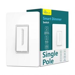
    I have a Treatlife DS01C Link, and wanted flash it so I can use it with home assistant. I realize now I made an error and thought it was on the list of devices, but it is not.

    What I did is:
    - Took device apart.
    - Used hot air to remove the WB3S from the board
    - Installed WB3S in my ESP8266 Adapter (I read online that the pinout is practically the same as an ESP-12F).
    - Used BK7231Flasher to make a back up
    - Flashed Openbeken UA_1.17.571.bin
    - Then realized that because I took the chip off the board it didn't get the GPIO layout.

    At that point I was like no biggie, it is in the devices list, to only discover it is not. So then I decided to solder the chip back on the board to do it the right way (I may have been too quick with that). Soldered back on, solder the TX, RX, 3.3V pin and GND directly to the Chip and connected to my computer with my FT232RL USB to TTL tool (3.3V).

    What I tried then is to reinstall the original firmware, to then flash it again to openbeken to be able to capture the GPIO layout.

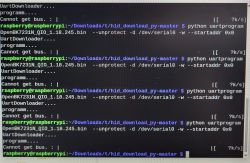
    This is where I am stuck, I get this error every time I try:
    Getting bus failed, will try again - 0/100!
    Getting bus failed, will try again - 1/100!
    Got exception: System.UnauthorizedAccessException: Access to the port is denied.
       at System.IO.Ports.InternalResources.WinIOError(Int32 errorCode, String str)
       at System.IO.Ports.SerialStream.get_BytesToRead()
       at System.IO.Ports.SerialPort.get_BytesToRead()
       at BK7231Flasher.BK7231Flasher.Start_Cmd(Byte[] txbuf, Int32 rxLen, Single timeout)!
    Exception caught: System.InvalidOperationException: The port is closed.
       at System.IO.Ports.SerialPort.get_BytesToRead()
       at BK7231Flasher.BK7231Flasher.consumePending()
       at BK7231Flasher.BK7231Flasher.Start_Cmd(Byte[] txbuf, Int32 rxLen, Single timeout)
       at BK7231Flasher.BK7231Flasher.linkCheck()
       at BK7231Flasher.BK7231Flasher.getBus()
       at BK7231Flasher.BK7231Flasher.doGetBusAndSetBaudRate()
       at BK7231Flasher.BK7231Flasher.doGenericSetup()
       at BK7231Flasher.BK7231Flasher.doReadAndWriteInternal(Int32 startSector, Int32 sectors, String sourceFileName, WriteMode rwMode)
       at BK7231Flasher.BK7231Flasher.doReadAndWrite(Int32 startSector, Int32 sectors, String sourceFileName, WriteMode rwMode)


    Openbeken seems to work fine, the device connected to my wifi etc. I just now have a device which does nothing. And it gave me this

    I was able to download the tuya config with the web application BK7231T_Tu...AB80A6.bin Download (72 kB) and got this template after the flash:

    {
    	"uart_baud":"9600",
    	"uart_databit":"3",
    	"uart_parity":"0",
    	"uart_stopbits":"1}l",
    	"bt_hid":"null",
    	"prod_test":"false "
    }


    I would greatly appreciate some guidance on next steps.

    Thanks.

    Ian
  • ADVERTISEMENT
  • #2 21071636
    p.kaczmarek2
    Moderator Smart Home
    The following may indicate that your device is TuyaMCU. No problem, TuyaMCU devices are supported, but they need a bit more of configuration.

    Would you be able to give some photos from inside your device so we can determine whether it's really a TuyaMCU?

    TuyaMCU guide is here:
    TuyaMCU flashing, setup and configuration guide - configure dpIDs for Home Assistant
    Can you familiarize yourself with it a bit?
    I would especially focus on paragraph 6:
    Screenshot showing a section of a webpage guide for configuring TuyaMCU. A code configuration card and a YouTube video are visible.

    PS: Still, we are not yet sure that your device is TuyaMCU. You may also have a simple UART-based dimmer, and that could complicate things a bit. They require some more research. However, I have already reverse engineered one: WXDM2 dual dimmer - reverse engineering - strange UART protocol

    Added after 1 [minutes]:

    PS2: Do you maybe have a 2MB flash backup, just in case, so in worst case, I could try flashing it onto my WB3S and capturing UART data (if that's not the TuyaMCU, but simple UART dimmer like WXDM2)?

    Added after 34 [minutes]:

    PS2: Wait, isn't it this device, or at least a variation of that: https://www.elektroda.pl/rtvforum/topic3825966.html I have config for that already.
    Helpful post? Buy me a coffee.
  • #3 21072075
    ianb
    Level 2  

    Hi,

    Thank you for your detailed reply. Just writing this quickly in my break, I will do more research as you suggested in my evening.

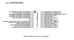
    The MCU is a BYD BF7812AM28-TJLX-P1Q6, I found the datasheet here: Link.

    Pin diagram of BF7812AM28-TJLX-P1Q6 chip.

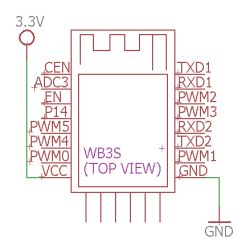
    Then I looked at the pinout of the WB3S:

    Pinout diagram of the WB3S module with pin labels and connections.

    What I found with my multimeter is:

    TXD1 from WB3S is connected to pin 14 from MCU
    RXD1 from WB3S is connected to pin 13 from MCU
    CEN from WB3S is connected to pin 8 from MCU
    EN from WBS3S is also (??) connected to pin 8 from MCU

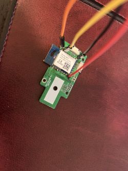
    Also attached the photos from the device.

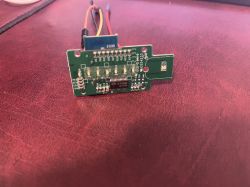
    This is the board with the WB3S
    WB3S module connected with wires to a green PCB.

    Other side
    Close-up of a WB3S circuit board with visible electronic components and connected wires.

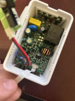
    Inside of the actual switch (relay), connected with ribbon cable to control board with WB3S
    View of the interior of a casing with electronics, including a main board with electronic components and connected cables.

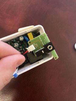
    Detail of the microswitch for the rocker
    Image of the interior of an electronic device with a visible circuit board and a connected cable.

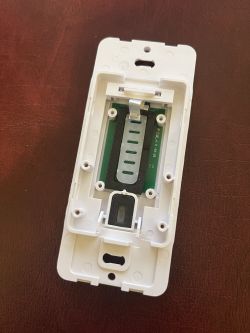
    And the inside of the rocker itself (I did not take this little board out, but it is connected via ribbon cable to WB3S board).
    Device panel with internal circuit board.

    EDIT: Forgot to add the backup which I indeed have

    EDIT 2: I also found this page on Tasmota, but I doubt it is the same still. The image of the board looks a lot different: Link Actually, maybe I am wrong, there is a hint in here: Link this is probably why I couldn't flash the WB3S attached to its board as the TX from the MCU is connected to the RX from the WB3S.
  • Helpful post
    #4 21072141
    p.kaczmarek2
    Moderator Smart Home
    Yes, this is TuyaMCU dimmer. I have a script for such a device here:
    https://www.elektroda.com/rtvforum/topic3898502.html
    The script from topic above should work.

    Please flash OBK and try.
    You may also add this line:
    
    tuyaMcu_defWiFiState 4
    
    Helpful post? Buy me a coffee.
  • ADVERTISEMENT
  • #5 21072230
    ianb
    Level 2  
    EDIT: PLEASE IGNORE, I AM A DUMBASS AND MISSED THAT THE DIMMING FUNCTION IS IN THE POP UP


    Thanks. I did that.

    I will let you know whether it works once I got it connected to mains.

    Using the MQTT config in home assistant I get the following error I can only find it in home assistant as an on/off switch.

    There's no dimmer slider as in your videos.

    I added this to my configuration.yaml

    
      light:
        - name: "Living Room Dimmer"
          state_topic: "lrdimmer/1/get"
          command_topic: "lrdimmer/1/set"
          brightness_command_topic: "lrdimmer/2/set"
          brightness_state_topic: "lrdimmer/2/get"
          brightness_scale: 99
          qos: 1
          payload_on: 1
          payload_off: 0
          retain: true
          optimistic: true


    Is this because I haven't got the whole switch together and only have the WB3S powered? Normally I see all of it when configured.

    Thanks.

    Ian
  • Helpful post
    #6 21072600
    p.kaczmarek2
    Moderator Smart Home
    Ah, I see, so....is everything working good now? Or can I help somehow more?
    Helpful post? Buy me a coffee.
  • #7 21072661
    ianb
    Level 2  

    Hi,

    Thanks for all your help. So far all seems fine when I power the chip. I reassembled the dimmer and going to install it. I didn't get to do it tonight as my wife had friends over and it tends to get awkward if I shut off power in the middle of their chats :).

    I will get back on here once installed to either confirm whether it is working, so it can be added to the device registry, or whether it needs additional tweaking. Either way you'll know. Thanks.

    Ian
  • Helpful post
    #8 21073031
    p.kaczmarek2
    Moderator Smart Home
    I think you can also enable TuyaMCU queue in the flags. And maybe add PowerSave 1 to autoexec.bat to reduce heating.
    Helpful post? Buy me a coffee.
  • ADVERTISEMENT
  • #9 21073682
    ianb
    Level 2  

    Hi,

    I installed the switch today and it works flawlessly. Also added the TuyaMCU queue flag and Powersave 1 in the autoexec.bat.

    So conclusion is that a Treatlife DS01C with a WB3S works with this configuration.

    Quick question, they also have a 3-pole version (for 3-way configurations) Link. Would the autoexec.bat be the same, or will it need an extra line?

    Thanks for all your help.

    Ian
  • #11 21073857
    p.kaczmarek2
    Moderator Smart Home
    What are the available values for dpID 4, enum here? Does it relate to the dimmer ramp? Linear or something else?

    Added after 8 [minutes]:

    ianb wrote:

    Quick question, they also have a 3-pole version (for 3-way configurations) Link. Would the autoexec.bat be the same, or will it need an extra line?

    I am not sure, but with OBK, any devices can be linked together to work either in groups or either like stairs switch... you don't even need to have a pair of the same model.

    Still, if you want to check them out, give it a go, we will help with configuration when they arrive.
    Helpful post? Buy me a coffee.
  • #12 21073867
    ianb
    Level 2  

    Hi, OK thanks!

    As this question:

    Quote:
    What are the available values for dpID 4, enum here?


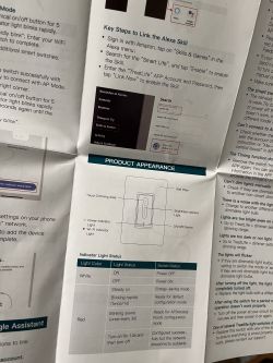
    This, although I am guessing, could be the status light in the bottom of the rocker switch. It can be either red or white. I have only ever seen it white on mine, but never installed it before flashing. See below page from the manual:

    User manual of a touch switch with an indicator light function description.
  • #13 21073892
    divadiow
    Level 34  
    p.kaczmarek2 wrote:
    >>21073857
    What are the available values for dpID 4, enum here? Does it relate to the dimmer ramp? Linear or something else?


    all DPIDs

    Code: JSON
    Log in, to see the code
  • #14 21073935
    p.kaczmarek2
    Moderator Smart Home
    Interestingly enough this device does not have a dpID for a start state (on, off, or 'remember last state'). I remember seeing it present on other TuyaMCU devices.
    Helpful post? Buy me a coffee.
  • #15 21074543
    ianb
    Level 2  

    It holds the dimming state even when switch is turned on/off.
  • ADVERTISEMENT
  • #16 21074861
    p.kaczmarek2
    Moderator Smart Home
    I was obviously referring to turning the power off (turning off the electricity), not to just doing ON/OFF in OBK web panel.
    Helpful post? Buy me a coffee.
  • #17 21075183
    ianb
    Level 2  
    Hi,

    I am going on holiday soon and like the switches to turn on and off by themselves without having my home assistant server turned on.

    I think I am on the right track, but not sure if I did it right, I am trying to get the light to turn on at sunset and turn off at 22:30 every day. See below autoexec I wrote:

    startDriver TuyaMCU
    setChannelType 1 toggle
    setChannelType 2 dimmer
    tuyaMcu_setDimmerRange 0 1000
    linkTuyaMCUOutputToChannel 1 1 1
    linkTuyaMCUOutputToChannel 2 2 2
    tuyaMcu_defWiFiState 4
    PowerSave 1
    
    startDriver ntp
    ntp_timeZoneOfs -07:00
    ntp_setLatlong Lat Long
    removeClockEvent 12
    removeClockEvent 13
    addClockEvent sunset 0xff 12 1 POWER ON
    addClockEvent 22:30:00 0xff 13 1 POWER OFF


    Is this correct?

    Also I didn't understand 2 things in the guideline:

    1. removeClockEvent, what does it precisely? It states to remove the event, but not sure why we need to do that?
    2. under addClockEvent in the command list there's this note that I need to compile with ENABLE_NTP_SUNRISE_SUNSET to make it work. How do I know whether I have this?

    Thanks.

    Ian
  • #18 21521805
    stvrdl
    Level 5  
    can this WB3S chip be flashed in place?

Topic summary

The discussion revolves around flashing the Treatlife DS01C smart dimmer switch with OpenBeken firmware (UA_1.17.571.bin) using BK7231Flasher. The user initially removed the WB3S chip from the board, flashed the firmware, and later re-soldered the chip to connect it to a computer for further configuration. The device was identified as a TuyaMCU dimmer, and users provided guidance on flashing, configuration, and troubleshooting. The user successfully reassembled the device, confirmed its functionality with Home Assistant, and inquired about configurations for a 3-pole version of the switch. Additional technical details included the use of MQTT for dimmer control and setting up automated on/off schedules.
Summary generated by the language model.
ADVERTISEMENT