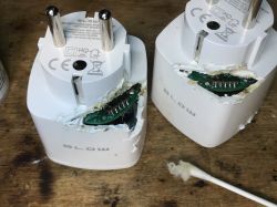
I will show you a little interesting fact - a quite invasive but effective way to change the firmware of the cheapest WiFi-controlled socket. This socket is characterized by a low price (PLN 30) and a structure that makes it impossible to remove the board with the WiFi module from inside, which makes changing the insert very difficult. This is not a product like Blitzwolf sockets, where we have either a hidden screw or retractable pins, here everything is held together and there is really no way to get to the programming pads. Normally I wouldn`t touch it, but I received a request from a reader to change the insert of such a socket at all costs ...
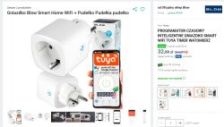
You can buy this socket really cheap and it`s not strange at all - it`s the cheapest option possible:
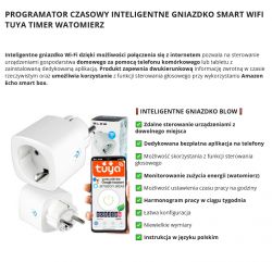
The socket offers energy measurement:
This is a variation of the LSPA9 socket, described here:
Electrical socket with LSPA9 energy measurement - we program our own firmware
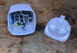
but this version has a grounding plate whose rivet makes it impossible to remove the PCB .
We`ll get to that in a moment, but first, photos of the packaging:
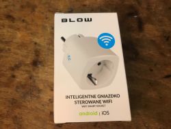
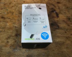
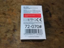
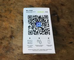
Set:
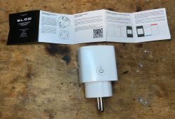
Polish-language instructions:





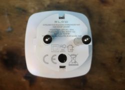
Socket itself:
ADVERTISEMENT
Interior and blow flashing
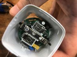
At first, they are disassembled like LSPA9, but after a while we have a surprise - the ground plate holds the rest of the system:
I don`t know how to make sense of this:
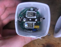
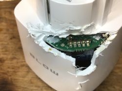
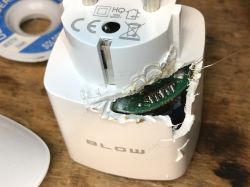
After consulting the reader, the decision was made - we cut:
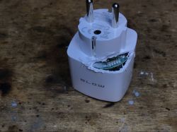
Already then I tried to connect with the programmer:
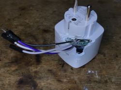
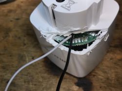
There is of course BK7231 inside, BK7231Flasher should be able to handle it:
https://github.com/openshwprojects/BK7231GUIFlashTool
but here is the problem, because the energy measurement system is probably on RX/TX... so you need to desolder the module:
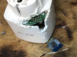
Outside the system, you can change the input normally:
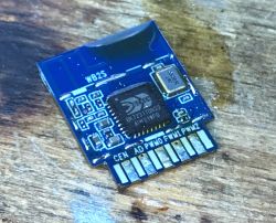
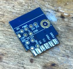
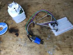
This is what the socket looks like from above:
The module returns to its place:
Flasher obviously detected the configuration:
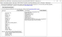
Verbal description:
Device configuration, as extracted from Tuya:
- BL0937 SEL on P24
- Button (channel 1) on P11
- LED (channel 1) on P10
- BL0937 VI on P8
- WiFi LED on P6
- BL0937 ELE on P7
- Relay (channel 1) on P26
Device seems to be using WB2S module, which is using BK7231T.
And the Tuya section starts, as usual, at 2023424
JSON Tuya:
Code: JSON
OBK template:
Code: JSON
After changing the firmware, you still need to perform calibration, similarly to Tasmota - CurrentSet, VoltageSet, PowerSet commands.
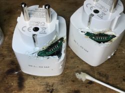
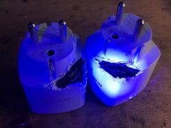
Finally, we protected the socket - first with a solder mask, and then (on the reader`s side) with epoxy or some form of filler, at our discretion:
Summary
Nothing to be proud of here, terrible load changing device. Very problematic, especially since now the products are no longer susceptible to the exploit allowing the first OTA via WiFi. I have very fond memories original LSPA9 where it was possible to remove the entire PCB from the housing. In the case of Blow, this is not possible due to the previously mentioned rivet plate.
It`s possible that something better could be invented, but I only programmed two pieces, so the method from the topic worked anyway.
What not to do to have automation operating fully locally, without the Chinese cloud...
Cool? Ranking DIY Helpful post? Buy me a coffee.


