logo elektroda
logo elektroda
X
logo elektroda

ONENUO WiFi Tuya Water Leak Sensor Flood Leakage Detector with Sound Alarm (898DT)

carlig833 1761 14
ADVERTISEMENT
  • #1 21087509
    carlig833
    Level 7  
    Hello,

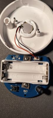
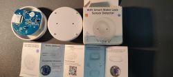
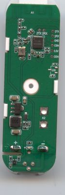
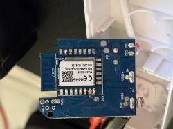
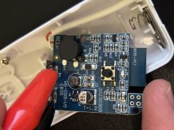
    I have bought this water leak, branded Tuya. Here are the pictures. Attached is the original firmware.
    I would like to make it free from the cloud and use it at home with my Wi-Fi.
    I'm not sure what to do next? I could not find a template for this device.
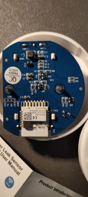
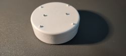
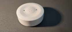
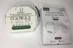
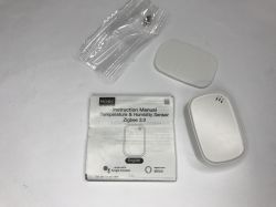
    Close-up of a Tuya water leak sensor circuit board showing electronic components. Image of the interior of a Tuya water leak sensor showing the circuit board and battery compartment. Photo of a Tuya brand Wi-Fi water leak sensor with its case removed and user manuals. White, round Tuya water leak sensor on a gray surface. Close-up of a white, circular Tuya water leak sensor on a dark surface.

    [Edit: added pictures of board after removing batteri case]
  • ADVERTISEMENT
  • #2 21087609
    p.kaczmarek2
    Moderator Smart Home
    Well, it seems that our tool is not able to extract the config at this time. So now you need to either investigate the PCB or play around with GPIO doctor (in the web app). Find out the role of each pin. We are looking for at least a LED Pin, water sensor pin (input), button pin, maybe more...
    Helpful post? Buy me a coffee.
  • #3 21088711
    carlig833
    Level 7  
    Hello,

    I could easily find a basic configuration of this device that works for the purpose, thanks to the following post about a similar device:
    https://www.elektroda.com/rtvforum/topic4054445.html

    Here is the device template in json format:

    
    {
      "vendor": "Tuya",
      "bDetailed": "0",
      "name": "ONENUO WiFi Tuya Water Leak Sensor",
      "model": " Flood Leakage Detector with Sound Alarm (898DT)",
      "chip": "BK7231N",
      "board": "TODO",
      "flags": "0",
      "keywords": [
        "water sensor",
        "ONENUO WiFi",
        "898DT"
      ],
      "pins": {
        "14": "Btn;2",
        "15": "WifiLED;0",
        "20": "BAT_Relay;4",
        "22": "dInput;1",
        "23": "BAT_ADC;5"
      },
      "command": "",
      "image": "https://obrazki.elektroda.pl/1039201300_1716148730.jpg",
      "wiki": "https://www.elektroda.com/rtvforum/topic4055031.html"
    }


    Here is the autoexec.bat

    
    Battery_Setup 2000 3000 2 2400 4096
    //measure batt every 2s
    Battery_cycle 2
    //mqtt_broadcastInterval 1
    //mqtt_broadcastItemsPerSec 5
    addEventHandler OnHold 10 SafeMode 5
    
    setChannelLabel 1 Water
    
    // now wait for MQTT
    waitFor MQTTState 1
    // extra delay, to be sure
    delay_s 1
    // publish water state at least once after boot
    publish 1 $CH1
    
    // if water detected, keep cycling (drains battery)
    // also useful for configuring the device or doing OTA
    again:
    delay_s 1
    if $CH1!=1 then goto again
    delay_s 5 // was 5
    
    // All good, sleep for 1 day
    PinDeepSleep 86400


    General flags:
    
    Flag 37 - [WiFi] Quick connect to WiFi on reboot (TODO: check if it works for you and report on github)


    Water detection works, deep sleep and periodic wake-up works, battery reports work.

    This device also features 80db alarm, but couldn't find how to make it work. Suggestions?
  • ADVERTISEMENT
  • #4 21088776
    p.kaczmarek2
    Moderator Smart Home
    Very good progress. Thanks for sharing!

    I think you can get buzzer working with PWM and PWMFrequency command. We've been actually talking about it in other topic few days ago:
    https://www.elektroda.com/rtvforum/find.php?q=PWMFrequency
    Here is one related link: https://www.elektroda.com/rtvforum/topic4052199-30.html#21077854

    Please try it out and let me know how it goes.
    Helpful post? Buy me a coffee.
  • #5 21092652
    carlig833
    Level 7  
    Ok, I had a look at the "related link" to learn how to test the buzzer.

    Unfortunately I don't know which PIN drives the buzzer.
    There is no meaningful information in json config extracted from original firmware backup.

    Thinking about the options, a brute force approach would be to test each and every pin, right?
    Given that this is a CBS module, and having read datasheet I deduce there are possibly 5 PINs for PWM:

    8 P8 I/O Support hardware PWM (Correspond to Pin 24 of the IC)
    9 P7 I/O Support hardware PWM (Correspond to Pin 23 of the IC)
    10 P6 I/O Support hardware PWM (Correspond to Pin 22 of the IC)
    11 P26 I/O Support hardware PWM (Correspond to Pin 15 of the IC)
    12 P24 I/O Support hardware PWM (Correspond to Pin 16 of the IC)

    (source: https://developer.tuya.com/en/docs/iot/cbu-module-datasheet?id=Ka07pykl5dk4u)

    Then I have:
    1) Enabled the "show raw pwm controllers" flag and rebooted the device
    2) Set "PWM" for PINs 8 to 12 in the PIN configuration page and common channel 6 in WebApps > Config > PinSettings
    3) exec command "PWMFrequency 1000" in the WebApp > Logs > Command
    4) exec command "setChannel 6 50" in the WebApp > Logs > Command

    I could not ear any sound from the device.

    Am I doing the correct steps?
  • ADVERTISEMENT
  • #6 21094648
    p.kaczmarek2
    Moderator Smart Home
    If done correctly, the following should be ok. You can check it with a, for example, LED and resistor connected to PWM pin. Changing the channel value should adjust the brightness of the LED.

    Maybe we need to investigate the PCB itself? How is the buzzer connected?
    Helpful post? Buy me a coffee.
  • #7 21095189
    divadiow
    Level 35  
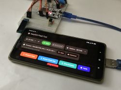
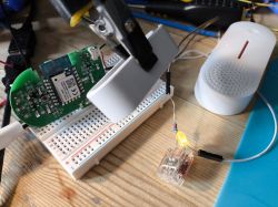
    I am playing with pwm for LED/buzzer for a door contact sensor at the moment. Maybe that needs its own thread though.

    Electronic circuit with a sensor and other components on a breadboard.
  • ADVERTISEMENT
  • #8 21095221
    p.kaczmarek2
    Moderator Smart Home
    Sure, please open thread for buzzer (or your device)

    Added after 44 [minutes]:

    >>21092652there are 6 PWMs I think, not 5. Did you check them all
    Helpful post? Buy me a coffee.
  • Helpful post
    #9 21096228
    carlig833
    Level 7  

    Buzzer of my water sensor is controlled by pin number 6 in WebApp > Config > Pin Settings. Here is the obk json config template:
    
    {
      "vendor": "Tuya",
      "bDetailed": "0",
      "name": "ONENUO WiFi Tuya Water Leak Sensor",
      "model": "Flood Leakage Detector with Sound Alarm (898DT)",
      "chip": "BK7231N",
      "board": "TODO",
      "flags": "0",
      "keywords": [
        "water sensor",
        "ONENUO WiFi",
        "898DT"
      ],
      "pins": {
        "6": "PWM;6",
        "14": "Btn;2",
        "15": "WifiLED;0",
        "20": "BAT_Relay;4",
        "22": "dInput;1",
        "23": "BAT_ADC;5"
      },
      "command": "",
      "image": "https://obrazki.elektroda.pl/1039201300_1716148730.jpg",
      "wiki": "https://www.elektroda.com/rtvforum/topic4055031.html"
    }


    I could manage to drive the buzzer to emulate a modulated bi-frequency siren. Here is the autoexec.bat:
    
    Battery_Setup 2000 3000 2 2400 4096
    //measure batt every 2s
    Battery_cycle 2
    //mqtt_broadcastInterval 1
    //mqtt_broadcastItemsPerSec 5
    addEventHandler OnHold 10 SafeMode 5
    setChannelLabel 1 Water
    // now wait for MQTT
    waitFor MQTTState 1
    // extra delay, to be sure
    delay_s 1
    // publish water state at least once after boot
    publish 1 $CH1
    // if water detected, keep cycling (drains battery)
    // also useful for configuring the device or doing OTA
    mainLoop:
    delay_s 1
    if $CH1!=1 then "goto sirenOn" else "goto sleep"
    // turn on the siren and goes into siren loop
    sirenOn:
    setChannel 6 10
    // siren loop repeats while water is detected
    sirenLoop:
    backlog PWMfrequency 460;delay_ms 50
    backlog PWMfrequency 491;delay_ms 50
    backlog PWMfrequency 521;delay_ms 50
    backlog PWMfrequency 550;delay_ms 50
    backlog PWMfrequency 577;delay_ms 50
    backlog PWMfrequency 601;delay_ms 50
    backlog PWMfrequency 621;delay_ms 50
    backlog PWMfrequency 638;delay_ms 50
    backlog PWMfrequency 650;delay_ms 50
    backlog PWMfrequency 657;delay_ms 50
    backlog PWMfrequency 660;delay_ms 50
    backlog PWMfrequency 657;delay_ms 50
    backlog PWMfrequency 650;delay_ms 50
    backlog PWMfrequency 638;delay_ms 50
    backlog PWMfrequency 621;delay_ms 50
    backlog PWMfrequency 601;delay_ms 50
    backlog PWMfrequency 577;delay_ms 50
    backlog PWMfrequency 550;delay_ms 50
    backlog PWMfrequency 521;delay_ms 50
    backlog PWMfrequency 491;delay_ms 50
    if $CH1!=1 then "goto sirenLoop" else "goto sirenOff"
    // turn off the siren and go into main loop
    sirenOff:
    setChannel 6 0
    goto mainLoop
    sleep:
    delay_s 5
    // All good, sleep for 1 day or next water event
    PinDeepSleep 86400


    I have removed all the "general flags" and I am currently running any of them.

    Lesson learned:
    1) Pin numbers in Tuya CBU datasheet does not match pin numbers in WebApp
    2) WebApp > Gpio Finder was very useful to guess where the buzzer was
    3) A little bit tricky to implement the buzzer tone. Here is a link to helper worksheet to build the code:
    https://docs.google.com/spreadsheets/d/1TK9gSiA_PeJN_Ib2-lEu-KJxAQaQPhOLzvdFuCchP-U/copy
  • #11 21096389
    p.kaczmarek2
    Moderator Smart Home
    Good job, I've also added your autoexec.bat to our samples:
    https://github.com/openshwprojects/OpenBK7231...mmit/5009cff8aa1e3c456f2a2595495366cd5f175fc7
    I didn't refresh docs yet, tough.

    Btw, @divadiow , if you have some time, you may consider adding some comments to existing autoexec samples. Just make sure to modify the source .bat file, and not the generated automatically MD document...
    Helpful post? Buy me a coffee.
  • #12 21096400
    divadiow
    Level 35  
    sure. as in, as I see some good ones around, like if I find a device not in devicelist?
  • #13 21096419
    p.kaczmarek2
    Moderator Smart Home
    There are two things that can be done to help:
    - adding comments to existing autoexec samples
    - adding new autoexec samples
    Helpful post? Buy me a coffee.
  • #15 21522747
    mariuszkowa
    Level 2  
    I have exactly the same device. I've used the provided pin configuration and uploaded the autoexec.bat. Thank you guys for providing those!
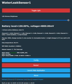
    It works great (detects water and produces audio signal) except for the fact that the device shows 4800mV which seems invalid for 2xAAA battery.
    @carlig833 do you see proper voltage?

    Water leak sensor control panel interface showing battery, voltage, temperature, and WiFi status.

    I don't think the LED Dimmer actually works (I don't see any difference on the LED) and not sure what is the "Toggle Light" control doing, but I don't really need those.
    Battery level on the other hand is a useful information to know when the batteries should be changed, so this one I'd like to fix, not sure how though.

    EDIT: The best configuration I've found that is showing "somewhat reasonable" voltage and percentage is to set pins this way (note pin BAT_ADC on the pin 24):
    
    "pins": {
        "6": "PWM;6",
        "15": "WifiLED;0",
        "20": "BAT_Relay;0",
        "22": "dInput;1",
        "24": "BAT_ADC;0"
      },
    

    And Battery Setup in the autoexec.bat like this:
    Battery_Setup 2200 2800 1.25 2400 4096


    Let me know if anyone got a better setup. This above shows low percentage when battery is getting low but I think there may be a better approach, just couldn't find it.

Topic summary

The discussion focuses on configuring the ONENUO WiFi Tuya Water Leak Sensor Flood Leakage Detector (model 898DT) to operate independently from the Tuya cloud, using local Wi-Fi control. Initial attempts to extract the device configuration from the original firmware were unsuccessful, prompting manual investigation of the PCB and pin functions using GPIO diagnostics. A basic JSON device template was shared, identifying key pins such as button (pin 14), WiFi LED (pin 15), battery relay (pin 20), digital input (pin 22), and ADC for battery voltage (pin 23). The buzzer control was determined to be on pin 6, configured for PWM output, enabling emulation of modulated siren sounds via custom autoexec.bat scripts. Users experimented with PWM settings to drive the buzzer and LED, confirming hardware capabilities and pin assignments. Battery voltage readings initially appeared inaccurate, leading to adjustments in pin assignments, particularly for the battery ADC input (pin 24), to improve measurement reliability. The community contributed improvements to configuration samples and firmware scripts, facilitating cloud-free operation and enhanced device control. Documentation and code samples were shared on GitHub and forum links for further development and testing.
Summary generated by the language model.
ADVERTISEMENT