Hello
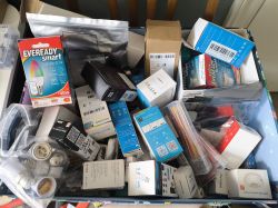
I've a number of devices that I haven't really dived into configuring to their full extent. I have bought quite a few devices for the thrill of opening, exploring and flashing but not for actual real-life use. Most are sitting in a big box - The Collection.
I'd like to change that because I need experience with configuring TuyaMCU devices, more complex autoexec files, modification of hardware to add LEDs, infra-red etc. I learn through trial-and-error rather than just reading.
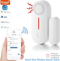
Anyway, the device in this thread is a battery-powered Tuya door/window contact sensor, of which some varieties are already in the device list with linked forum threads. This one comes with a buzzer, however.
https://www.aliexpress.com/item/1005005340141460.html

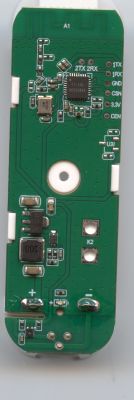
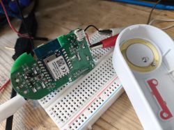
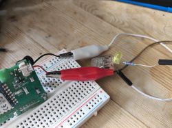
Upon opening we see a BK7231N CB3S, the button, an LED, the magnet bar sensor thing and the connector to the piezo buzzer fit to the front half of the chassis. In this pic I've already unsoldered the buzzer because it gets annoying in testing. An LED (with 220Ohm resistor) replaces it for now.
Firstly, I need to dump the factory firmware and work out the pin assignments. Using a multimeter these are identified:
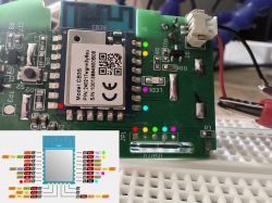
and using TX2 the factory fw boot log is
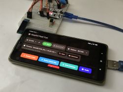
A dump using TX1 and RX1 is attached. This appears to be some kind of custom firmware, so no automatic pin extraction was successful using Easy UART Flasher.
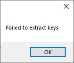
using what is in dump however we can query Tuya's API for its response. Data in bin:
AW301_UI_CB3S2 - schema ID: 000004hgep
Contact Sensor (mcs)
and unusually it includes an update URL, though the version already installed on the device supersedes the download version
After some more multimeter and trial-and-error GPIO finder action:
P6 - magnet sensor
P7 - Wifi LED
P9 - Buzzer
P21 - BAT_Relay
P23 - BAT_ADC
P26 - Button
OK, fine. Now what? Things in my head at this stage:
-how do I most effectively set deep sleep? (assuming battery use and no mod to use USB power)
-using the button to wake from sleep
-using the buzzer to sound alarm
-how long after magnet status change should the buzzer sound? should the wifi LED flash for a while as a warning before the buzzer?
-how to even make the buzzer buzz
-can the buzzer make a tune instead of an annoying monotonous noise?
-if integrating with HA how often should device wake to report battery status
-what happens if the device reboots at the time the door/window is open (sensor state is 1)? Does it buzz as soon as it's running again?
-what's for lunch?
After flashing to OBK I set the basic config up in the module config. P7, P21, P23, P26 and confirmed they were as expected. I am using a 3v external PSU clamped to the battery contacts, so the 3v at this stage is consistent (you'd think). The battery_setup that puts me closest to 3v at 100% "charge" is
These values mean Battery_Setup [minbatt][maxbatt][V_divider][Vref][AD Bits]

There are some other threads in progress regarding buzzers, PWM and water leak sensors which I believe would help with this device. eg
https://www.elektroda.com/rtvforum/topic4055031.html
https://www.elektroda.com/rtvforum/topic4052199.html
Fast-forward a little because I can't remember all the steps to this point, below is my current autoexec.bat. At this point the pin assignments are configured as
"6": "DoorSnsrWSleep_nPup;0",
"7": "WifiLED_n;4",
"9": "PWM;5",
"21": "BAT_Relay;1",
"23": "BAT_ADC;3",
"26": "Btn_ScriptOnly;2"
-DoorSnsrWSleep_nPup because the led (will be buzzer) stays lit regardless with DoorSnsrWSleep
-PWM set on the buzzer pin because that will be used in the autoexec to sound alarm
-Btn_ScriptOnly so there is no on/off button in the GUI
-Flags 3 (it's the PWM we're interested in, not the light sliders), 10, 37, 42 (without sensor would show door open (state 1) if magnet was next to sensor)

and the behaviour in reality:
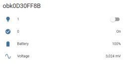
the power-up check state entries successfully sets the LED on/off depending on sensor state also.
that's as far as I've gone for now.
I've a number of devices that I haven't really dived into configuring to their full extent. I have bought quite a few devices for the thrill of opening, exploring and flashing but not for actual real-life use. Most are sitting in a big box - The Collection.

I'd like to change that because I need experience with configuring TuyaMCU devices, more complex autoexec files, modification of hardware to add LEDs, infra-red etc. I learn through trial-and-error rather than just reading.
Anyway, the device in this thread is a battery-powered Tuya door/window contact sensor, of which some varieties are already in the device list with linked forum threads. This one comes with a buzzer, however.
https://www.aliexpress.com/item/1005005340141460.html

Upon opening we see a BK7231N CB3S, the button, an LED, the magnet bar sensor thing and the connector to the piezo buzzer fit to the front half of the chassis. In this pic I've already unsoldered the buzzer because it gets annoying in testing. An LED (with 220Ohm resistor) replaces it for now.


Firstly, I need to dump the factory firmware and work out the pin assignments. Using a multimeter these are identified:

and using TX2 the factory fw boot log is
Code: Text
A dump using TX1 and RX1 is attached. This appears to be some kind of custom firmware, so no automatic pin extraction was successful using Easy UART Flasher.

using what is in dump however we can query Tuya's API for its response. Data in bin:
Code: Text
AW301_UI_CB3S2 - schema ID: 000004hgep
Contact Sensor (mcs)
and unusually it includes an update URL, though the version already installed on the device supersedes the download version
Code: Text
After some more multimeter and trial-and-error GPIO finder action:
P6 - magnet sensor
P7 - Wifi LED
P9 - Buzzer
P21 - BAT_Relay
P23 - BAT_ADC
P26 - Button
OK, fine. Now what? Things in my head at this stage:
-how do I most effectively set deep sleep? (assuming battery use and no mod to use USB power)
-using the button to wake from sleep
-using the buzzer to sound alarm
-how long after magnet status change should the buzzer sound? should the wifi LED flash for a while as a warning before the buzzer?
-how to even make the buzzer buzz
-can the buzzer make a tune instead of an annoying monotonous noise?
-if integrating with HA how often should device wake to report battery status
-what happens if the device reboots at the time the door/window is open (sensor state is 1)? Does it buzz as soon as it's running again?
-what's for lunch?
After flashing to OBK I set the basic config up in the module config. P7, P21, P23, P26 and confirmed they were as expected. I am using a 3v external PSU clamped to the battery contacts, so the 3v at this stage is consistent (you'd think). The battery_setup that puts me closest to 3v at 100% "charge" is
Code: Text
These values mean Battery_Setup [minbatt][maxbatt][V_divider][Vref][AD Bits]
There are some other threads in progress regarding buzzers, PWM and water leak sensors which I believe would help with this device. eg
https://www.elektroda.com/rtvforum/topic4055031.html
https://www.elektroda.com/rtvforum/topic4052199.html
Fast-forward a little because I can't remember all the steps to this point, below is my current autoexec.bat. At this point the pin assignments are configured as
"6": "DoorSnsrWSleep_nPup;0",
"7": "WifiLED_n;4",
"9": "PWM;5",
"21": "BAT_Relay;1",
"23": "BAT_ADC;3",
"26": "Btn_ScriptOnly;2"
-DoorSnsrWSleep_nPup because the led (will be buzzer) stays lit regardless with DoorSnsrWSleep
-PWM set on the buzzer pin because that will be used in the autoexec to sound alarm
-Btn_ScriptOnly so there is no on/off button in the GUI
-Flags 3 (it's the PWM we're interested in, not the light sliders), 10, 37, 42 (without sensor would show door open (state 1) if magnet was next to sensor)

Code: Text
and the behaviour in reality:
the power-up check state entries successfully sets the LED on/off depending on sensor state also.
that's as far as I've gone for now.


