logo elektroda
logo elektroda
X
logo elektroda

How to Replace WB3S with esp8266 in HBN 36ft String Lights?

brianroy86 1149 26
ADVERTISEMENT
  • #1 21105935
    brianroy86
    Level 6  
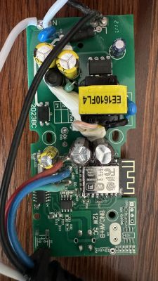
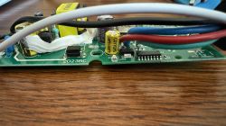
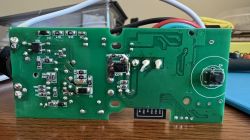
    Hello all, I have done a teardown of the HBN 36ft String Lights. I am trying to replace the brains from the WB3S that it came with to an esp8266, however I think I need to do something to cut the Tuya MCU's out of the mix. Could I please get some help identifying what it is that I need to do in order to get this working? I can provide additional images as needed.
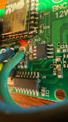
    PCB with electronic components for HBN 36ft string lights. Close-up view of a circuit board from HBN 36ft String Lights with multicolored wires and a 2023BC marking. Close-up view of a PCB with electronic components.
  • ADVERTISEMENT
  • #2 21105946
    p.kaczmarek2
    Moderator Smart Home
    What kind of device is that? Is it RGB? RGB+CW? And if so, is RGB individually adressible or all LEDs are the same color?

    How are LEDs connected?
    Helpful post? Buy me a coffee.
  • ADVERTISEMENT
  • #3 21105961
    brianroy86
    Level 6  
    They are individually addressable lights, RGB-WW lights. It runs off of mains, there's a converter to drop it down to 5v, but the mains power runs through the cord and there is a plug at the far end of the LEDs so you can use it as an extension cord of sorts. However when I swapped the chip out and plugged it in, I still see the same effects as it had when the W3BS was there so the Tuya MCU must still be going something.

    Edit: the leds are connected via those 3 wires, red green and blue.
  • #4 21106087
    p.kaczmarek2
    Moderator Smart Home
    Why are you replacing BK, OBK already supports this kind of device...?

    Still.. for Tasmota, you need to desolder the TuyaMCU totally and connect DIN of LEDs to your ESP.

    Which of the SOIC chips on board is connected to RX/TX of the WiFi module and to the DIN of LEDs?
    Helpful post? Buy me a coffee.
  • #5 21106092
    brianroy86
    Level 6  

    I'm replacing because I want to use wled.

    As for the other questions, how would I find that out? Can you tell by the images?
  • #7 21106125
    brianroy86
    Level 6  

    I do have one yes

    Added after 44 [minutes]:

    >>21106125Also the main reason I wanted to do this was because each time these lights get unplugged, or I lose power I need to re-set up these lights in the tuya app. It's as if it doesn't have any persistent memory and restarts everything on power loss.
  • ADVERTISEMENT
  • #8 21108668
    brianroy86
    Level 6  
    How would I use the multimeter to test this?
  • #9 21108673
    p.kaczmarek2
    Moderator Smart Home
    Disconnect all power, set multimeter to continuity test (with beep), and put one probe on RX1 or TX1 of WiFi module and check with second probe to which IC it connects (it beeps)
    Helpful post? Buy me a coffee.
  • #10 21108684
    brianroy86
    Level 6  

    Sorry, I'm still not following. I don't know what an IC is. Could you show me with the images I uploaded what I would connect it to? I understand to put the multimeter in continuity mode and touch one probe to rx or tx, but I'm not sure what I'm touching with the other probe. Trying to learn as I go here :)
  • #11 21108722
    p.kaczmarek2
    Moderator Smart Home
    IC = integrated circuit = this little one black thing with 8 legs (4 on right side, 4 on left). You have two of them on board.
    Helpful post? Buy me a coffee.
  • #12 21108780
    brianroy86
    Level 6  
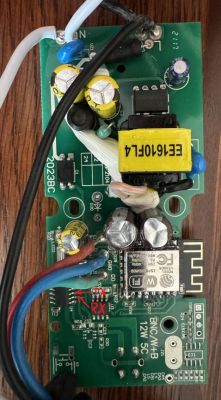
    OK, so I've done some testing and here's the results.

    GPIO1 is connected to the 6th leg on the top row
    GPIO3 is connected to the 7th leg on the top row

    These are the pins near the label U4

    Edit for clarification
    PCB with visible components, connectors, and markings.
  • #13 21108795
    p.kaczmarek2
    Moderator Smart Home
    Ok and to which leg does DO wire (marked as DO on PCB) connects to?
    Helpful post? Buy me a coffee.
  • #14 21108807
    brianroy86
    Level 6  

    It does not appear to be connected to any of them, can't get a beep out of the multimeter on either IC
  • #15 21108811
    p.kaczmarek2
    Moderator Smart Home
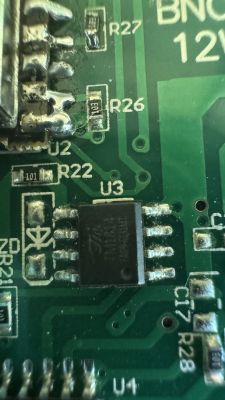
    okay so what is the marking on U3 chip?
    Helpful post? Buy me a coffee.
  • #16 21108833
    brianroy86
    Level 6  
    Close-up of a circuit board with visible electronic components and traces.
    It’s tough to see but here
  • #17 21108854
    p.kaczmarek2
    Moderator Smart Home
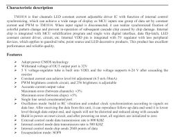
    TM1814..
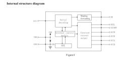
    Technical documentation of the TM1814 chip Block diagram of the internal structure of an integrated circuit with inputs and outputs.
    usage:
    Typical application circuit for TM1814.
    Does WLED supports TM1814?
    https://github.com/Aircoookie/WLED/issues/1519
    Hmmm maybe it does?
    https://github.com/search?q=repo%3AAircoookie%2FWLED%20TM1814&type=code
    Yea, it seems so...

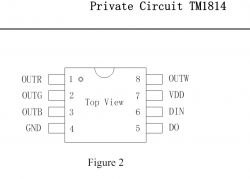
    So now,. where is the DIN leg connected?
    Diagram of TM1814 integrated circuit with pin labeling.
    DIN leg is probably connected to second IC (black large one with many legs), but where?


    You will have to remove that second large black IC (TuyaMCU) but you have to keep in place TM1814.

    Later we will need to connect TM1814 via DIN to ESP, but first we will need to read on how to connect it.

    Added after 1 [minutes]:

    PS: related link for future testing: https://github.com/Aircoookie/WLED/issues/3514
    Helpful post? Buy me a coffee.
  • #18 21108884
    brianroy86
    Level 6  
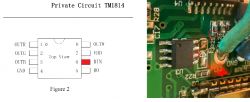
    Image of a circuit board with visible electronic components and a pin connection marked in red.

    I'm not sure if I'm looking at it upside down or not, but I believe that pin connects here
  • #19 21108949
    p.kaczmarek2
    Moderator Smart Home
    it seems ok:
    Diagram of TM1814 and photo of a PCB with a marked integrated circuit and connections.
    Now you need to remove TuyaMCU (U4, black IC with many legs), can you do that? Do you know how to do it without breaking the PCB?
    Helpful post? Buy me a coffee.
  • #20 21108975
    brianroy86
    Level 6  

    I believe I can do it yes. I have a solder braid on the way from AliExpress, I would just put the braid on the pins and heat it up with the iron to suck up the solder, then it should just lift off. It seems a little too tight in there to go at it with a heat gun. I'd end up knocking something else off by mistake.

    Does that sound like a solid plan? Also after I remove that IC, would I have to make any other changes or bridges?
  • ADVERTISEMENT
  • #21 21109028
    p.kaczmarek2
    Moderator Smart Home
    I think we also need to investigate how is the button connected. Also with multimeter. And connect it to ESP.

    Do you have flux? Flux is necessary. Also some Pb solder on pins can help. Don't forget the flux.

    Also we need to read about ESP to know which PIN do we have to use TM1814 DIN. I have a feeling that it was TX, but I may be wrong.
    Helpful post? Buy me a coffee.
  • #22 21109042
    brianroy86
    Level 6  
    My solder is this which says pb37, and I have plenty of flux.
    https://a.co/d/5zC1Xny

    I’ll try to see what that button is connected to, not home at the moment.

    Thank you so much for your help so far, I’m learning a lot as we work through this!
  • #23 21109140
    p.kaczmarek2
    Moderator Smart Home
    You can just heat up both sides of WiFi module:


    Helpful post? Buy me a coffee.
  • #24 21110878
    brianroy86
    Level 6  

    Haven't removed the IC yet but the bottom right pin on the IC with 16 legs is connected to the button. Closest to C11 on the IC near U4
  • #25 21110880
    p.kaczmarek2
    Moderator Smart Home
    so the button will also be needed to be routed to ESP
    Helpful post? Buy me a coffee.
  • #26 21111063
    brianroy86
    Level 6  

    Would I just do that with wire? Or is there a better way to do it?
  • #27 21111091
    p.kaczmarek2
    Moderator Smart Home
    You will need to get a small wire, strip the insulation, and solder it either to button pin directly or to the pad where was big IC and solder second wire end to one of the unused ESP pins. Of course, do not use RX/TX for that purpose, just some generic GPIO that is easily accessible.
    Helpful post? Buy me a coffee.

Topic summary

The discussion revolves around replacing the WB3S microcontroller in HBN 36ft String Lights with an ESP8266 to enable the use of WLED firmware. The user seeks assistance in removing the Tuya MCU, which appears to be causing issues with persistent memory, requiring reconfiguration after power loss. Participants suggest using a multimeter to identify connections between the ESP8266 and the integrated circuits (ICs) on the board, specifically the TM1814 LED driver. The process involves desoldering the Tuya MCU and connecting the TM1814's DIN pin to the ESP8266. Additionally, the button functionality needs to be routed to a GPIO pin on the ESP8266. The user is advised to use soldering techniques and flux for the desoldering process.
Summary generated by the language model.
ADVERTISEMENT