Updated: 2023/12/27
The IR Codes captured on Tasmota with new compact encoding scheme can be played back as it is through IRSend. See the updates below
Reference Links about S06 IR Blaster:
Teardown, flashing and configuration for Smart Tuya IR Blaster S06 [CB3S]
OpenBeken configuration for WiFi universal IR remotes from aliexpress (S06, S18, IRC02) with BK7231
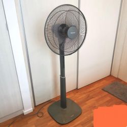
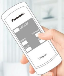
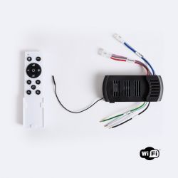
I have a requirement to be able to capture/send IR RAW data to make my Panasonic Fan working.
Since IR RAW feature will take some time to appear in OpenBeken, I decided to go the hard way.
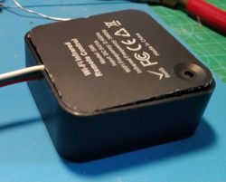
I had a S06 with CB3S Module.
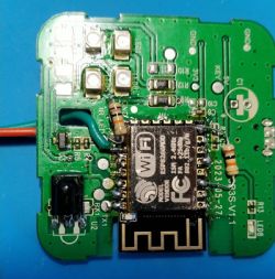
When you inspect the CB3S Module alongside ESP-12F you could see a perfect match for critical PINs like Power, Chip Enable and Reset.
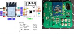
So I decided to replace the CB3S Module with ESP-12F Module.
I first flashed tasmora_ir.bin image on to ESP-12F (There are plenty of tutorials available on flashing ESP-12F module on the internet).
I did not do a very good job in de-soldering and soldering in the new module. It was the first time for me to use the heat gun and I accidentally blew off a tiny SMD resistor and a capacitor in the process. Hopefully I can do a better job next time
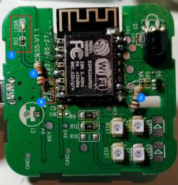
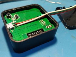
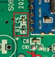
I blew up R3 & C5 [4] during the process. These are connected to RESET button on the device. For the moment the RESET button is trivial for me as I can always power cycle the device externally. Perhaps I will make some corrections later to the hardware.
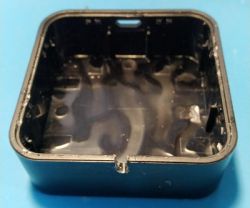
Needed to solder 10k pullup/pulldown resistors as shown for Chip Enable [1] and GPIO15 [2] as shown.
One more issue remains. I could not get the LED8 [3] to light up. When I touch the R13 with a tweezer the LED gets lit up faintly. The output on GPIO4 where the LED is connected to toggles between 0V and 3.2V ish value correctly. Need to see whether R13 needs to be changed. Again this is a trivial matter for me at the moment.
Tasmota Setup:
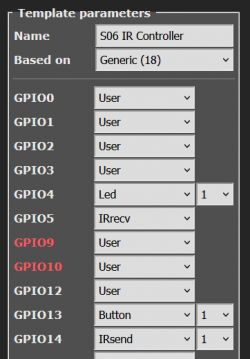
Enabled Option58 for receiving RAW data.
Update:
The following conversion is not required. We can directly play back the above raw data string received
-------------------------------------------------------------------------------
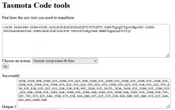
The RAW data received can be converted in to a string which can be transmitted using IRSend command using the following tool:
https://tasmota.hadinger.fr/util
-------------------------------------------------------------------------------
Data received in following RAW Date message can be played back:
I did a further optimization by deleting parts of the string from the end, working backwards until I find a +/- symbol. When you press the remote you might press it too longer than required. So the extra data stream can be removed like this on trial & error basis. This way you can figure out the minimum length of data string to play back. See the example of Tasmota rule for the final outcome.
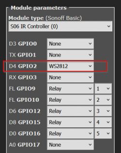
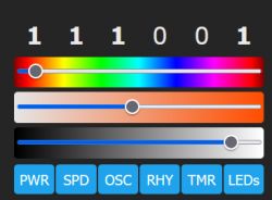
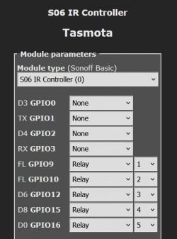
Defined 5 x Virtual Relays using unused GPIOs to be used as Buttons on WebGUI:
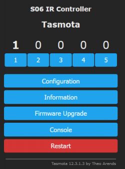
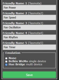
Changed the labels on the buttons:
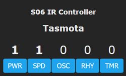
Created Tasmota Rules for button toggles (here is an example for PWR and SPEED buttons:
Now the Fan can be controlled via Web URL or MQTT using POWER1, POWER2, POWER3, POWER4, POWER5 commands.
The IR Codes captured on Tasmota with new compact encoding scheme can be played back as it is through IRSend. See the updates below
Reference Links about S06 IR Blaster:
Teardown, flashing and configuration for Smart Tuya IR Blaster S06 [CB3S]
OpenBeken configuration for WiFi universal IR remotes from aliexpress (S06, S18, IRC02) with BK7231
I have a requirement to be able to capture/send IR RAW data to make my Panasonic Fan working.
Since IR RAW feature will take some time to appear in OpenBeken, I decided to go the hard way.
I had a S06 with CB3S Module.
When you inspect the CB3S Module alongside ESP-12F you could see a perfect match for critical PINs like Power, Chip Enable and Reset.

So I decided to replace the CB3S Module with ESP-12F Module.
I first flashed tasmora_ir.bin image on to ESP-12F (There are plenty of tutorials available on flashing ESP-12F module on the internet).
I did not do a very good job in de-soldering and soldering in the new module. It was the first time for me to use the heat gun and I accidentally blew off a tiny SMD resistor and a capacitor in the process. Hopefully I can do a better job next time

I blew up R3 & C5 [4] during the process. These are connected to RESET button on the device. For the moment the RESET button is trivial for me as I can always power cycle the device externally. Perhaps I will make some corrections later to the hardware.

Needed to solder 10k pullup/pulldown resistors as shown for Chip Enable [1] and GPIO15 [2] as shown.
One more issue remains. I could not get the LED8 [3] to light up. When I touch the R13 with a tweezer the LED gets lit up faintly. The output on GPIO4 where the LED is connected to toggles between 0V and 3.2V ish value correctly. Need to see whether R13 needs to be changed. Again this is a trivial matter for me at the moment.
Tasmota Setup:

Enabled Option58 for receiving RAW data.
21:32:50.903 CMD: SetOption58 1
21:32:50.906 RSL: RESULT = {"SetOption58":"ON"}

21:32:56.983 RSL: RESULT = {"IrReceived":{"Protocol":"UNKNOWN","Bits":78,"Hash":"0x94972B6F","Repeat":0,"RawData":"+3525a+830-2700Bc+825-935DcBcDcBeDeBeDeDeB-2695BeDeDcBeDeDeDcDc+845-2675DfBcDeD-39350+3565-3485DfBcDeDcDc+850hDeL-910D-940DeDeDcBeDeDcDeDeDeBfDcDcDfDcDeDiA-3520DcDcDeDcL-2670+855pLmDnLmDeDnDcQmLmLpDnDeDeLpDcLpQpLpLmD","RawDataInfo":[155,155,0]}}
Update:
The following conversion is not required. We can directly play back the above raw data string received
-------------------------------------------------------------------------------
The RAW data received can be converted in to a string which can be transmitted using IRSend command using the following tool:
https://tasmota.hadinger.fr/util

-------------------------------------------------------------------------------
Data received in following RAW Date message can be played back:
21:32:56.983 RSL: RESULT = {"IrReceived":{"Protocol":"UNKNOWN","Bits":78,"Hash":"0x94972B6F","Repeat":0,"RawData":"+3525a+830-2700Bc+825-935DcBcDcBeDeBeDeDeB-2695BeDeDcBeDeDeDcDc+845-2675DfBcDeD-39350+3565-3485DfBcDeDcDc+850hDeL-910D-940DeDeDcBeDeDcDeDeDeBfDcDcDfDcDeDiA-3520DcDcDeDcL-2670+855pLmDnLmDeDnDcQmLmLpDnDeDeLpDcLpQpLpLmD","RawDataInfo":[155,155,0]}}IRSend 0, +3525a+830-2700Bc+825-935DcBcDcBeDeBeDeDeB-2695BeDeDcBeDeDeDcDc+845-2675DfBcDeD-39350+3565-3485DfBcDeDcDc+850hDeL-910D-940DeDeDcBeDeDcDeDeDeBfDcDcDfDcDeDiA-3520DcDcDeDcL-2670+855pLmDnLmDeDnDcQmLmLpDnDeDeLpDcLpQpLpLmDI did a further optimization by deleting parts of the string from the end, working backwards until I find a +/- symbol. When you press the remote you might press it too longer than required. So the extra data stream can be removed like this on trial & error basis. This way you can figure out the minimum length of data string to play back. See the example of Tasmota rule for the final outcome.
Defined 5 x Virtual Relays using unused GPIOs to be used as Buttons on WebGUI:


Changed the labels on the buttons:
02:36:18.449 CMD: WebButton1 PWR
02:36:18.454 RSL: RESULT = {"WebButton1":"PWR"}
02:36:29.105 CMD: WebButton2 SPD
02:36:29.110 RSL: RESULT = {"WebButton2":"SPD"}
02:36:39.275 CMD: WebButton3 OSC
02:36:39.281 RSL: RESULT = {"WebButton3":"OSC"}
02:36:53.438 CMD: WebButton4 RHY
02:36:53.443 RSL: RESULT = {"WebButton4":"RHY"}
02:37:03.340 CMD: WebButton5 TMR
02:37:03.344 RSL: RESULT = {"WebButton5":"TMR"}

Created Tasmota Rules for button toggles (here is an example for PWR and SPEED buttons:
Rule1
ON POWER1#STATE DO IRSend 0,+3500-3550+875-2650+880dC-885CdCdC-2645EfC-890CfEfCfCdEfCfCdCfCfCfCdCdCdCgEdCfC
  ENDON
ON POWER2#STATE DO IRSend 0,+3500-3550+855-2670CdC-910+850dFdCdCdFdCdCdCdFeC-905CeCdCeCeFeCeFeFeCgCeCdC ENDON
Now the Fan can be controlled via Web URL or MQTT using POWER1, POWER2, POWER3, POWER4, POWER5 commands.
Cool? Ranking DIY


