logo elektroda
logo elektroda
X
logo elektroda

Config? - Atorch GR2P-W/S/L Smart DIN Rail Meter (BK7231N) (CB2S) (CH573F) (BL0942)

bbb34 3648 13
ADVERTISEMENT
  • #1 21124081
    bbb34
    Level 2  
    Hello Everybody!

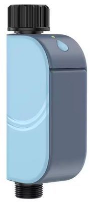
    My mailbox received some DIN Rail Energy monitors from Aliexpress:
    - Atorch GR2P-W/S/L

    DIN Rail Energy monitor Atorch GR2P with display.

    Close-up of the Atorch DIN Rail Energy monitor display with measurement data.

    The buttons, menus, and display appearance are strikingly similar to the Atorch S1-B/W/T/H.
    I also got the S1, which I was able to flash and configure with the help of the discussion at https://www.elektroda.com/rtvforum/topic4003739.html . Thanks a lot to the contributors there!

    The GR2P is easy to open with two screws on the bottom.
    Inside, there is a stack of the display on top of the PCB with a block of black foam in between.
    Close-up view of the interior of a DIN Rail Energy Monitor with exposed PCB module and protective foam.

    A CB2S is mounted through the PCB from below. The foam sticks to both, the display and the board.
    To get to the component side of the board, one has to peel off the foam block. The adhesive is somewhat strong, some residues of foam stuck to the components.

    On the board, there are the following ICs:
    - CHF573F (RISC-V MCU)
    - BL0942 (Metering IC)
    - PN8015 (Power Management)

    I didn't try to flash the CB2S in place. It came out easily with the help of desoldering braid and gravity.
    After flashing and soldering it back into the device, the wifi node and the openbeken web app came up as expected.

    Now I am stuck. I tried the configuration for similar devices, including:
    - Atorch S1 (https://www.elektroda.com/rtvforum/topic4003739.html). This one has a CB3S.
    - Tuya LSPA9 (https://www.elektroda.com/rtvforum/topic3887748.html).
    - quite a few other energy meters

    None of these worked. I didn't get any measurements.

    Any ideas how to proceed?

    Close-up of Atorch energy meter display with graph and measurement data.

    Close-up of the Atorch GR2PW energy monitor display showing the settings menu.
  • ADVERTISEMENT
  • #2 21124298
    p.kaczmarek2
    Moderator Smart Home
    It's a very nice device, we can make this work together.
    First of all, have you seen the TuyaMCU generic guide?
    https://www.elektroda.com/rtvforum/topic4038151.html
    This should give you a basic overview of the process.

    Since this device is already flashed, you can with guessing baud rate and requesting dpIDs with tuyaMcu_sendQueryState command.
    Helpful post? Buy me a coffee.
  • #3 21125321
    bbb34
    Level 2  
    Thanks for the hint! I dumped the backup image on extractor in the flash tool, and it said 
    {
    "baud":"9600"
    }
    Probably I could have guessed that as well.   :)

    autoexec.bat wrote:

    startDriver TuyaMCU
    startDriver NTP
    ntp_setServer 172.25.1.1
    ntp_timeZoneOfs +01:00
    tuyaMcu_setBaudRate 9600
    setChannelType 0 Toggle_Inv
    setChannelType 1 ReadOnly
    setChannelType 2 Voltage_div100
    setChannelType 3 Power_div100
    setChannelType 4 Current_div1000
    setChannelType 5 Frequency_div100
    setChannelType 6 EnergyTotal_kWh_div1000
    setChannelType 7 Temperature
    setChannelType 8 PowerFactor_div100
    setChannelType 9 EnergyTotal_kWh_div1000
    linkTuyaMCUOutputToChannel 131 enum 0
    linkTuyaMCUOutputToChannel 1 bool 1
    linkTuyaMCUOutputToChannel 20 1 2
    linkTuyaMCUOutputToChannel 19 1 3
    linkTuyaMCUOutputToChannel 18 1 4
    linkTuyaMCUOutputToChannel 133 1 5
    linkTuyaMCUOutputToChannel 102 1 6
    linkTuyaMCUOutputToChannel 135 1 7
    linkTuyaMCUOutputToChannel 134 raw 8
    linkTuyaMCUOutputToChannel 123 1 9


    User interface of obkRegMeterL1 displaying measurement data and Toggle buttons.


    I get measurements in both web app and to the mqtt server (no load connected). Perfect!
  • ADVERTISEMENT
  • #4 21125351
    p.kaczmarek2
    Moderator Smart Home
    9600 is a default baud, it should work without any specific settings.

    Is everything working as expected? I can see your config is missing the setting of default WiFi state 0x04. By default, it's set only when MQTT is connected.
    Helpful post? Buy me a coffee.
  • ADVERTISEMENT
  • #5 21125450
    bbb34
    Level 2  
    I realize that I posted the wrong autoexec. It was the last from the S1 instead of the GR2P.
    I corrected that above: Baud rate is 9600 and 'mqtt_broadcastInterval 5' is not there. Sorry for the confusion!

    You are right that it works with the default baud rate without tuyaMcu_setBaudRate. It was just there because I copied from the S1.

    I don't know why the main page shows two toggle buttons. I'm using the device without any switch.

    But yes, everything that is there seems to work!

    I didn't know about the WiFi state 0x04, but I think that showing the MQTT state is the best for my use case.
  • #6 21125455
    p.kaczmarek2
    Moderator Smart Home
    Maybe you still have "Toggle" channel types set? Check in the web app.
    Helpful post? Buy me a coffee.
  • #7 21483898
    morgan_flint
    Level 14  
    Hello, @bbb34 !

    Searching for the thread I started some time ago on the same device, I've found that you had started this one before...

    Just writing this to tell you that, in case you haven't already come over it, you can find there more information about this device's DpIDs and configuration
  • ADVERTISEMENT
  • #8 21647307
    viniciusmbs
    Level 3  
    Hello, my friend. Thank you for sharing your post!

    I saw the topic you created and I would like to ask for your help.
    I have an ATORCH GR2PW that went offline. It appears in the Smart Life app, but it fails to connect and is blinking slowly.

    My device details:

    Model: ATORCH GR2PW (Wi-Fi smart socket with power meter)

    Wi-Fi Module: LN-02 (Beken BK7231N)

    Chipset: BK7231N QFN32 → 32-bit ARM Cortex-M4F, 120 MHz, with 2.4 GHz Wi-Fi

    I would like to know if I can use the information from your post to try to recover my device.
    In your opinion, would it be possible to apply the same techniques you described in your topic (such as manual configuration or installing alternative firmware like OpenBeken) to “save” my device?

    Thank you very much for any guidance you can provide!
  • #9 21647389
    divadiow
    Level 36  
    viniciusmbs wrote:
    Wi-Fi Module: LN-02 (Beken BK7231N)


    LN-02? This is known to have a Lightning Semi LN882H chip, rather than Beken. Do you have a pic?

    LN-02 electronic module with Lightning Semi LN882H chip on wooden surface
  • #10 21647450
    viniciusmbs
    Level 3  
    >>21647389 No, the GR2PW really uses a CB2S module (you can see the marking on the Wi-Fi module in the first photo). It worked for a month: my Home Assistant was running perfectly, pulling data from the solar panels and the device, and providing my consumption data. What could have happened? Suddenly, it went offline, and I deleted it from the app.
    When I open Tuya or Smart Life, it is recognized immediately, but it keeps trying to connect and eventually fails. The green LED blinks slowly. I tried putting it in AP mode, but nothing worked. I don’t know how to make it blink fast.
    The chip you showed me is an LN-02. Thank you for your time and for the response.
    Close-up of a circuit board with a CB2S Wi-Fi module and three electrolytic capacitors.
    Electronic module with connected wires and visible PCB marked CB2S mounted in a smart device enclosure.
    Close-up of GR2PW device PCB with visible connectors, wires, and Wi-Fi and power module labels.

    I even went as far as replacing one of the 16V 220µF capacitors to see if it would start working again. I’m planning to replace the other two 450V 4.7µF capacitors to see if that helps, because I have some Tuya devices that were like this and came back to life. They were swollen, but these ones look fine visually.
  • #11 21647478
    p.kaczmarek2
    Moderator Smart Home
    Capacitors often fail in Tuya devices, but if that's not it, then probably you can try OBK...
    Helpful post? Buy me a coffee.
  • #12 21647925
    viniciusmbs
    Level 3  
    >>21647478 Hello @p.kaczmarek2, first of all, thank you for your reply. My name is Vinicius, I’m from Brazil. I will study your documentation carefully, and congratulations on your initiative. I am replacing all the capacitors; even though they look fine, one of them might be failing. If in the end I cannot get a connection with Smart Link, I will try Tasmota. I just want the device to connect, because without it I cannot integrate the consumption graphs in Home Assistant with my solar production.
    Device pairing screen showing ATORCH S with retry message in Portuguese.
    App screen showing error adding ATORCH Smart Energy device.

    Just one more question: these two ferrite components, it looks like something is missing. Is that normal?
    Close-up of PCB with two missing ferrite elements marked by red arrows

    Added after 1 [hours] 57 [minutes]:

    It's very strange: it is recognized by Smart Life at first, but in the end it fails. I’ve tried every possible way, even in AP mode. It creates the network, but it doesn’t connect to the app.


    In the video below, the connection light keeps blinking slowly and it doesn’t enter fast pairing mode.


  • #13 21648543
    morgan_flint
    Level 14  
    viniciusmbs wrote:
    Just one more question: these two ferrite components, it looks like something is missing. Is that normal?

    I've just answered this question here
  • #14 21657131
    viniciusmbs
    Level 3  
    >>21647478 @p.kaczmarek2, Gentlemen, please excuse my ignorance. In my case, the chip is a CB2S with a GR2PW meter. Can I use the firmware BK7231N UART Flash OpenBK7231N_QIO_1.18.168.bin?
    I bought a PL2303 USB adapter. Can I solder directly to the Wi-Fi chip on the board of my GR2PW?
    Would this allow it to reconnect and be accepted again by the Smart Life app?

Topic summary

The discussion focuses on configuring the Atorch GR2P-W/S/L Smart DIN Rail Energy Meter, which shares interface similarities with the Atorch S1 series. The device contains a CB2S module mounted on the PCB beneath the display, separated by adhesive foam. Users successfully accessed the device's firmware and identified the default UART baud rate as 9600, enabling communication without additional baud rate settings. Configuration and flashing were facilitated using TuyaMCU tools, including querying device property IDs (dpIDs). The MQTT integration works correctly, providing measurement data to both a web app and MQTT server. Some UI anomalies, such as unexpected toggle buttons, were attributed to channel type settings in the web app. The importance of setting the default WiFi state (dpID 0x04) was noted, although the MQTT connection state was preferred for the user's application. Additional resources and previous threads provide further details on dpIDs and device configuration.
Summary generated by the language model.
ADVERTISEMENT