Hello to all!
I recently bought this one for my collection, got it very cheap on sale, but the normal price is also good Link:

I found it interesting, compared to the other two similar devices I've been playing with (TOMPD63-WIFI and TOMPD63-LW because of the graphic screen. OTOH, it doesn't have residual current measurement (this version, at least, as we'll see later). Anyway, I don't think software-based RCBOs like those two should replace "conventional" (or this better kind of smart ones), because of safety reasons.
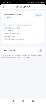
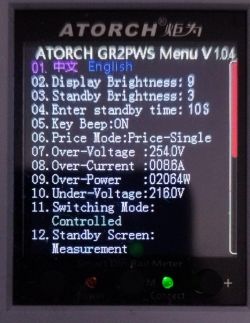
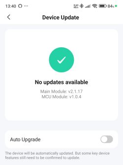
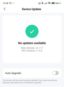
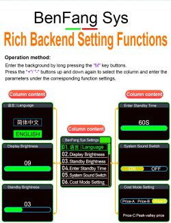
Ok, let's start with a print of the description from the advertisement (in case the link gets broken), enclosed as the first attachment. It includes a good gallery of screenshots from the device itself and the Tuya app, so I'll skip my own related photos. Also, here's a link to the manual from the manufacturer's page (also attached, in case the link breaks).
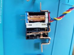
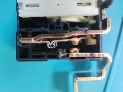
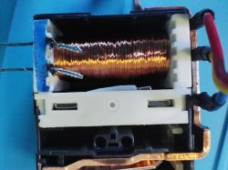
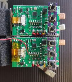
Now, the teardown gallery:
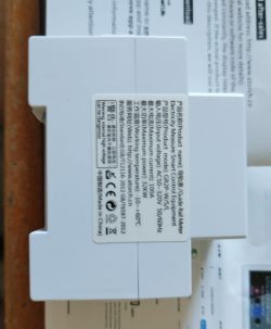
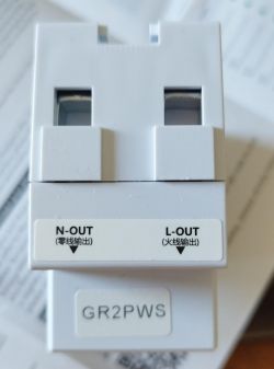
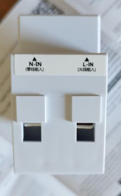
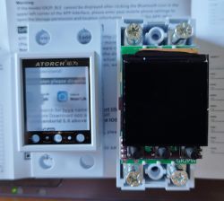
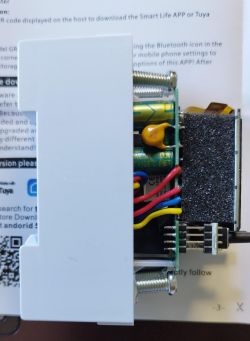
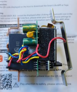
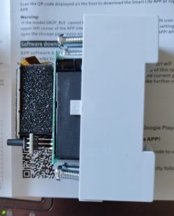
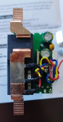
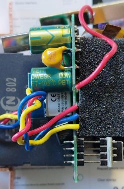
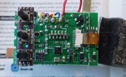
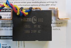
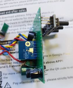
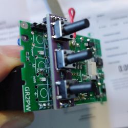
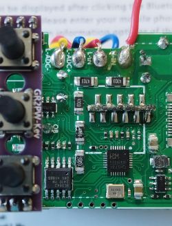
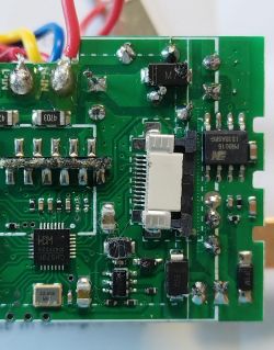
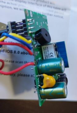
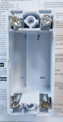
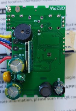
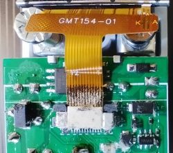
As we can see, it uses the CB2S WiFi module (datasheet), which employs BK7231N chip, so it is possible to flash OpenBeken on it.
As for the rest of main components, we can see them in the following image:
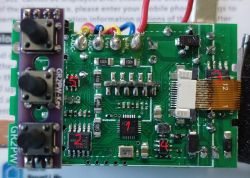
"1" (CH573F) is the Tuya MCU.
"2" (BL0942) is the AC metering chip
"3" (PN8016) is an unisolated DC/DC switch mode converter, to get 9V (presumably, as this is the relay's coil voltage) from the rectified AC (measured 10.1V).
"4" (marked HAHA A) is a switched mode regulator, to get (presumably) 3.3V (measured 3.23) from the previous 9V converter. This one feeds the Tuya MCU, the WiFi module, and the Power indicator LED. I couldn't find anything meaningful related to the markings but, from the peripheral components and connections could be similar to SY21031
or RT6200
"5" (marked 762A) is the bistable relay driver (Chinese datasheet)
Other main components are the relay and the TFT graphic screen (labeled GMT154-01, similar to this one).
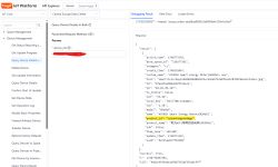
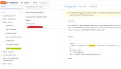
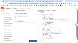
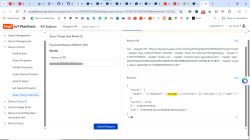
Now, let's continue with the DpIDs identification. Following my tutorial, this is the result of "Query Things Data Model", once formatted and translated:
That means a total of 44 DpID's!! Let's put them in a more legible format:
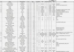
(also attached as pdf)
After doing this with the original FW, we can now proceed to make a backup of it (attached) and then flash OBK. I tried first without isolating CB2S TX1 and RX1 signals from the main PCB, but got errors. I managed to isolate them without removing the module (just cleaning the solder bridge) and kept soldered Vcc and GND (CEN signal was already isolated). I have to say I had some problems trying to flash with bk7231flasher_1.3.3 (freezing at a certain point), so I finally did it with 1.1.6.
With so many DpIDs, this is still "work in progress". I've found some of them don't seem to work. Others, supposedly read-write, behave as read-only, etc. But the autoexec.bat at this moment is the following:
As you can see in some of the comments, this one is derived from the TOMPD63-LW's autoexec, which works well with @Angel0fDeath web page for TOMPD63-WIFI, provisional adapted version. For this reason, and anticipating the possibility of adapting that web page also for this device, I've tried to keep the same channels for the same sensors.
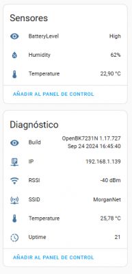
These are screenshots of OBK's main screen and Home Assistant page for this device:
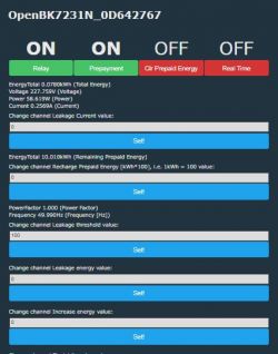
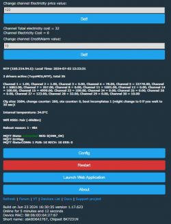
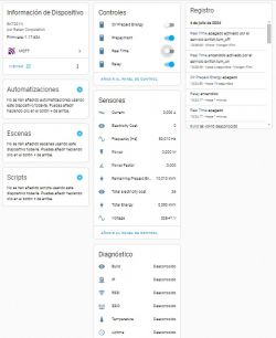
Everything seems to work fine (except for "strange" DpIDs) and I am able to properly command the relay, read network parameters, program values, etc.
And this is all for now. As there aren't enough channels to map all 44 DpIDs, I've been using channel 30 to test other DpIDs but still have to decide which of them will be chosen for the final mapping (as I said before, some of them don't work and others don't seem to have a real function). I'll keep you informed of the results!https://www.elektroda.com/rtvforum/posting.php?mode=editpost&p=21142057#
EDIT (18/07/24): I´ve been making some progress with the device, and I think I'm almost at the point of considering the work finished ("almost" because you can always find something to add/improve when dealing with this things...). So, the changes are:
1.- (almost) definitive autoexec.bat:
Also attached as GR2PWS_autoexec.bat_p.txt. I would recommend clearing all comments when copying to little FS to save space there.
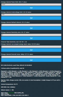
This is the aspect of OBK's main page:
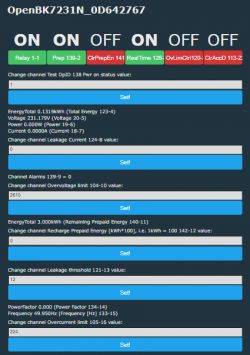
 .
.
(the labels in these screenshots do not correspond with the autoexec, as it's a debug version that includes channel numbers and DpIDs to facilitate debugging)
And from Home Assistant's device page:
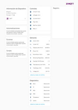
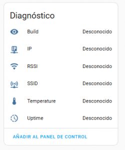
BTW, @p.kaczmarek2 , in this page all the diagnostics sensors appear like "unknown", while in OBK's main page they have values. What could be the cause?
Also, I see there's no channel type for currency... Do you think it would be interesting to add a "generic currency" channel type? (I understand adding it for all the main currencies would mean too many types).
2.- Custom web page, modified from @Angel0fDeath versions for the other devices cited before, attached as GR2PWS_rev3pr.html.txt. Heavily commented, so the original author can check/validate the mods, if he wants. I'd also clear all comments if loading it to little FS on the device, to avoid space problems.
Here is the screenshot of this custom web page:
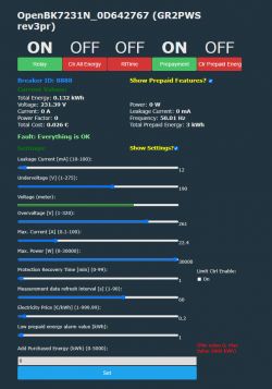
One comment about this: The fault treatment in this device (DpID 132) is completely different than from the other two devices cited at the beginning, as in this one type is "enum", and in those it was "bitmap". The consequences are that in the other ones, several faults (overcurrent and overvoltage, for example) could be signaled at once, while in this device only one at a time, in the order of priority overvoltage-overcurrent-overpower-undervoltage-low prepaid energy-leakage" (if we have overcurrent and overvoltage, for example, it will show overvoltage and, once this disappears, then it'd show overcurrent, if still persisting).
3.- I've also updated the table of DpIDs with more info:
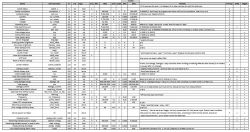
Also attached as .pdf (deleted previous one). If someone would like to have the original spreadsheet (.xlsx), just ask.
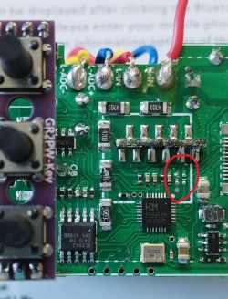
I´ve left a good amount of DpIDs out from the .bat (and .HTML), as there are not enough channels in OBK to accommodate all of them, nor they're really needed for normal remote operation. Also, although the necessary hardware is not implemented, for now, I've left the DpI'd related to the leakage current, as I've seen in the PCB that there's space left for the associated components, and I may give a try to install them and check if the TuyaMCU's firmware is prepared to read leakage current. To use the device as is, comment out or delete these lines in the .bat and .html.
Also, after writing my original post, I found there were already two posts about other Atorch products, with similar characteristics, especially the first one, but with some differences in DpIDs and functionality: AT4P(WP/BW) Smart Energy monitor, and S1-B/W/T/H Smart Socket Energy Monitor. The autoexec's posted there used only a small subset of the full range.
I see there have been no comments on this thread since I first posted it ... Anyway, I hope it can be of help to others who buy this interesting device, and I'll PM @gulson to see if he can put it in the devices list (I don't know if I can do it by myself)
Finally, many thanks to @p.kaczmarek2 again for this fantastic software that gives so many possibilities to experiment with these devices!!
I recently bought this one for my collection, got it very cheap on sale, but the normal price is also good Link:

I found it interesting, compared to the other two similar devices I've been playing with (TOMPD63-WIFI and TOMPD63-LW because of the graphic screen. OTOH, it doesn't have residual current measurement (this version, at least, as we'll see later). Anyway, I don't think software-based RCBOs like those two should replace "conventional" (or this better kind of smart ones), because of safety reasons.
Ok, let's start with a print of the description from the advertisement (in case the link gets broken), enclosed as the first attachment. It includes a good gallery of screenshots from the device itself and the Tuya app, so I'll skip my own related photos. Also, here's a link to the manual from the manufacturer's page (also attached, in case the link breaks).
Now, the teardown gallery:


As we can see, it uses the CB2S WiFi module (datasheet), which employs BK7231N chip, so it is possible to flash OpenBeken on it.
As for the rest of main components, we can see them in the following image:

"1" (CH573F) is the Tuya MCU.
"2" (BL0942) is the AC metering chip
"3" (PN8016) is an unisolated DC/DC switch mode converter, to get 9V (presumably, as this is the relay's coil voltage) from the rectified AC (measured 10.1V).
"4" (marked HAHA A) is a switched mode regulator, to get (presumably) 3.3V (measured 3.23) from the previous 9V converter. This one feeds the Tuya MCU, the WiFi module, and the Power indicator LED. I couldn't find anything meaningful related to the markings but, from the peripheral components and connections could be similar to SY21031
or RT6200
"5" (marked 762A) is the bistable relay driver (Chinese datasheet)
Other main components are the relay and the TFT graphic screen (labeled GMT154-01, similar to this one).
Now, let's continue with the DpIDs identification. Following my tutorial, this is the result of "Query Things Data Model", once formatted and translated:
Code: JSON
That means a total of 44 DpID's!! Let's put them in a more legible format:

(also attached as pdf)
After doing this with the original FW, we can now proceed to make a backup of it (attached) and then flash OBK. I tried first without isolating CB2S TX1 and RX1 signals from the main PCB, but got errors. I managed to isolate them without removing the module (just cleaning the solder bridge) and kept soldered Vcc and GND (CEN signal was already isolated). I have to say I had some problems trying to flash with bk7231flasher_1.3.3 (freezing at a certain point), so I finally did it with 1.1.6.
With so many DpIDs, this is still "work in progress". I've found some of them don't seem to work. Others, supposedly read-write, behave as read-only, etc. But the autoexec.bat at this moment is the following:
Code: Javascript
As you can see in some of the comments, this one is derived from the TOMPD63-LW's autoexec, which works well with @Angel0fDeath web page for TOMPD63-WIFI, provisional adapted version. For this reason, and anticipating the possibility of adapting that web page also for this device, I've tried to keep the same channels for the same sensors.
These are screenshots of OBK's main screen and Home Assistant page for this device:


Everything seems to work fine (except for "strange" DpIDs) and I am able to properly command the relay, read network parameters, program values, etc.
And this is all for now. As there aren't enough channels to map all 44 DpIDs, I've been using channel 30 to test other DpIDs but still have to decide which of them will be chosen for the final mapping (as I said before, some of them don't work and others don't seem to have a real function). I'll keep you informed of the results!https://www.elektroda.com/rtvforum/posting.php?mode=editpost&p=21142057#
EDIT (18/07/24): I´ve been making some progress with the device, and I think I'm almost at the point of considering the work finished ("almost" because you can always find something to add/improve when dealing with this things...). So, the changes are:
1.- (almost) definitive autoexec.bat:
Code: Javascript
Also attached as GR2PWS_autoexec.bat_p.txt. I would recommend clearing all comments when copying to little FS to save space there.
This is the aspect of OBK's main page:

 .
.
(the labels in these screenshots do not correspond with the autoexec, as it's a debug version that includes channel numbers and DpIDs to facilitate debugging)
And from Home Assistant's device page:

BTW, @p.kaczmarek2 , in this page all the diagnostics sensors appear like "unknown", while in OBK's main page they have values. What could be the cause?
Also, I see there's no channel type for currency... Do you think it would be interesting to add a "generic currency" channel type? (I understand adding it for all the main currencies would mean too many types).
2.- Custom web page, modified from @Angel0fDeath versions for the other devices cited before, attached as GR2PWS_rev3pr.html.txt. Heavily commented, so the original author can check/validate the mods, if he wants. I'd also clear all comments if loading it to little FS on the device, to avoid space problems.
Here is the screenshot of this custom web page:

One comment about this: The fault treatment in this device (DpID 132) is completely different than from the other two devices cited at the beginning, as in this one type is "enum", and in those it was "bitmap". The consequences are that in the other ones, several faults (overcurrent and overvoltage, for example) could be signaled at once, while in this device only one at a time, in the order of priority overvoltage-overcurrent-overpower-undervoltage-low prepaid energy-leakage" (if we have overcurrent and overvoltage, for example, it will show overvoltage and, once this disappears, then it'd show overcurrent, if still persisting).
3.- I've also updated the table of DpIDs with more info:

Also attached as .pdf (deleted previous one). If someone would like to have the original spreadsheet (.xlsx), just ask.
I´ve left a good amount of DpIDs out from the .bat (and .HTML), as there are not enough channels in OBK to accommodate all of them, nor they're really needed for normal remote operation. Also, although the necessary hardware is not implemented, for now, I've left the DpI'd related to the leakage current, as I've seen in the PCB that there's space left for the associated components, and I may give a try to install them and check if the TuyaMCU's firmware is prepared to read leakage current. To use the device as is, comment out or delete these lines in the .bat and .html.
Also, after writing my original post, I found there were already two posts about other Atorch products, with similar characteristics, especially the first one, but with some differences in DpIDs and functionality: AT4P(WP/BW) Smart Energy monitor, and S1-B/W/T/H Smart Socket Energy Monitor. The autoexec's posted there used only a small subset of the full range.
I see there have been no comments on this thread since I first posted it
Finally, many thanks to @p.kaczmarek2 again for this fantastic software that gives so many possibilities to experiment with these devices!!
Cool? Ranking DIY


