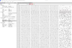
I have another device to play with!
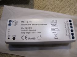
This is Tuya SPI LED controller with up to 4 data lines (LED strip controller depending) supporting up to 1000 LEDs @ 8 amps. Its model is WT-SPI and a quick Google shows a few vendors for it.
https://www.aliexpress.com/item/1005005335498067.html

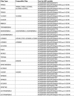
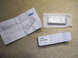
The product manual is quite good and is also available as a PDF, which I attach. The number of supported LED controller types seems quite extensive
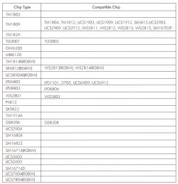
I didn't know some LED types come with separate data and clock lines, which is why there is C01/D01 & C02/D02
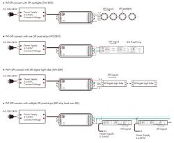
Despite having a CBU/BK7231N module the device also comes with an MCU. The accepted input voltage is 5-24v with barrel or bare-wire connector options. With my 12V DC barrel adaptor the output is 12v, so natively good for LED strips that require 12v, like WS2811.
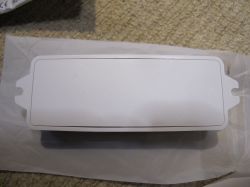
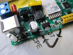
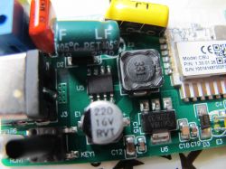
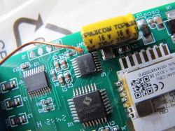
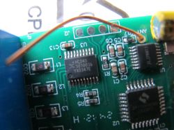
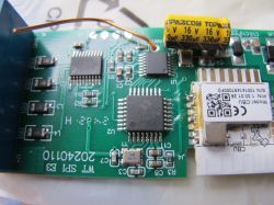
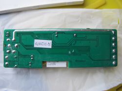
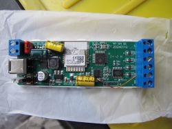
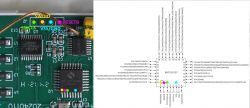
I think I have identified these components correctly
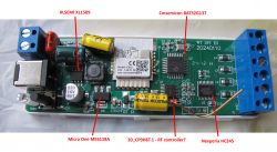
Along with their respective product pages:
https://www.xlsemi.com/datasheet/XL1509-EN.pdf
http://www.microne.com.cn/en/product/246.html
https://www.mcu.com.cn/en/Products/112
https://www.nexperia.com/products/analog-logi...ers/transceivers/series/74HC245-74HCT245.html
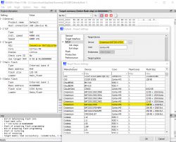
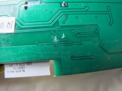
Because the MCU is connected to the CBU using RX and TX communication at 115200 baud, I was not able to take a dump of the CBU firmware without severing the TX trace to the MCU. Unfortunately I severed the RX too, I think I've usually only needed to do one before. No matter, it can be repaired.
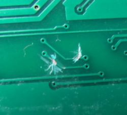
And with the MCU out of the way I can take a backup, attached. Also, boot log:
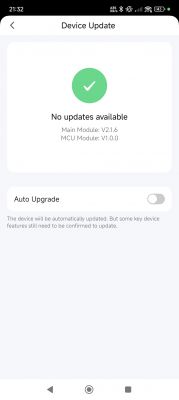
Being v2.1.6 it is not patched and so Cloudcutter can be used to flash to Openbeken. My next steps are to repair the RX/TX and begin MCU communication capture using TuyaMCU Analyser. I have not been able to get a full API response from Tuya for this device so I'll have to use tuyaMcu_sendQueryState as explained here https://www.elektroda.com/rtvforum/topic4049908.html
I am curious to find out if the MOSI pin on the CBU is doing anything. Is the MCU doing everything and does it contain the full program of supported LED controller types and animation seen in the Tuya app? If so, can all these things be set by MCU command alone from within Openbeken? If so, it could mean a long autoexec and many GUI options to set in OBK. Sadly that would mean no OBK PixelAnim opportunities I fear.
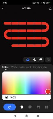
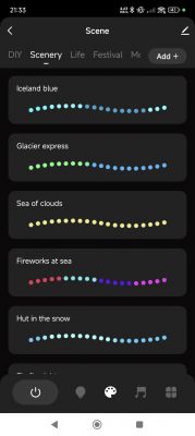
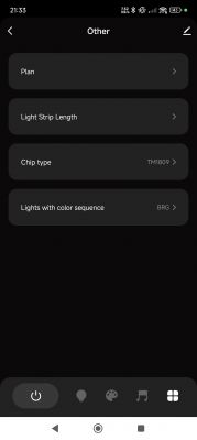
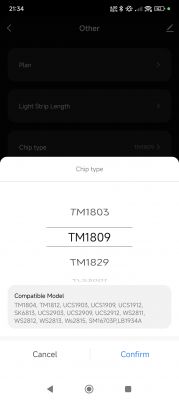
This is Tuya SPI LED controller with up to 4 data lines (LED strip controller depending) supporting up to 1000 LEDs @ 8 amps. Its model is WT-SPI and a quick Google shows a few vendors for it.
https://www.aliexpress.com/item/1005005335498067.html

The product manual is quite good and is also available as a PDF, which I attach. The number of supported LED controller types seems quite extensive

I didn't know some LED types come with separate data and clock lines, which is why there is C01/D01 & C02/D02

Despite having a CBU/BK7231N module the device also comes with an MCU. The accepted input voltage is 5-24v with barrel or bare-wire connector options. With my 12V DC barrel adaptor the output is 12v, so natively good for LED strips that require 12v, like WS2811.


I think I have identified these components correctly

Along with their respective product pages:
https://www.xlsemi.com/datasheet/XL1509-EN.pdf
http://www.microne.com.cn/en/product/246.html
https://www.mcu.com.cn/en/Products/112
https://www.nexperia.com/products/analog-logi...ers/transceivers/series/74HC245-74HCT245.html
Because the MCU is connected to the CBU using RX and TX communication at 115200 baud, I was not able to take a dump of the CBU firmware without severing the TX trace to the MCU. Unfortunately I severed the RX too, I think I've usually only needed to do one before. No matter, it can be repaired.

And with the MCU out of the way I can take a backup, attached. Also, boot log:
Code: Text
Being v2.1.6 it is not patched and so Cloudcutter can be used to flash to Openbeken. My next steps are to repair the RX/TX and begin MCU communication capture using TuyaMCU Analyser. I have not been able to get a full API response from Tuya for this device so I'll have to use tuyaMcu_sendQueryState as explained here https://www.elektroda.com/rtvforum/topic4049908.html
I am curious to find out if the MOSI pin on the CBU is doing anything. Is the MCU doing everything and does it contain the full program of supported LED controller types and animation seen in the Tuya app? If so, can all these things be set by MCU command alone from within Openbeken? If so, it could mean a long autoexec and many GUI options to set in OBK. Sadly that would mean no OBK PixelAnim opportunities I fear.


