In my never ending pursuit to collect everything I have obtained one of these neutral/no neutral Bouffalo Labs BL602-based smart switches. It's a single channel Cozylife DS-1321AL.
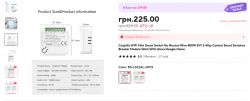
https://www.aliexpress.com/item/1005006150931509.html
Model: WiFi Switch Module
Input: AC100-240V 50/60Hz
Current: 10A
LED: Max 400W/Gang
Operation temp: -10℃-+40℃
Case temp:Tc: +80℃ (Max)
Dims (LxWxH):47.3x20x47.3 mm
Inside is a module I have not had or seen before. It has 1 mention on Elektroda in a post from @Zain00 and one from @Zhekos555 here.
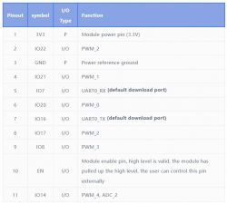
The DT-BL02 looks to have something to do with Cozylife but the XT-BL02, which is referenced on the RF shield, is by Shenzhen Xiaoteng Technology Co. Datasheet attached.
https://cozylife.app/product/zh/hardware/wifi/dt-bl02.html
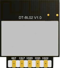
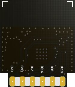
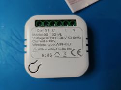
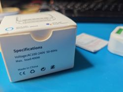
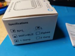
Some general pics first.
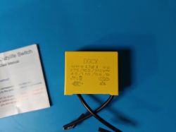
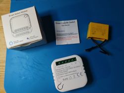
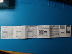
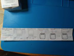
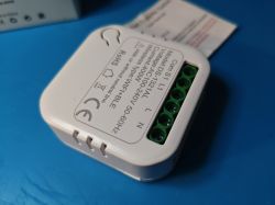
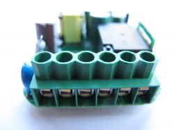
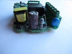
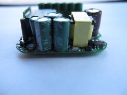
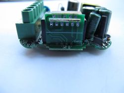
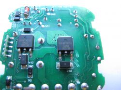
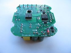
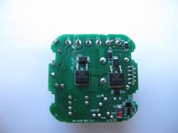
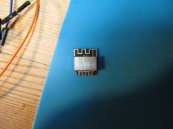
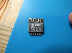
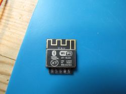
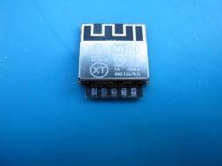
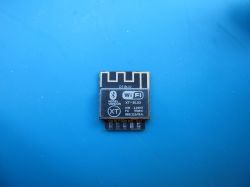
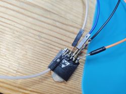
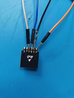
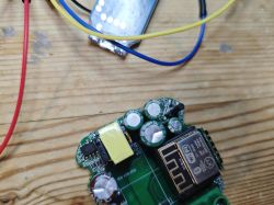
and with the module soldered up to the USB-TTL adaptor, the log out was captured:
and with D8 pulled high with a 10k resistor in circuit the factory firmware was dumped using BLDevCube 1.8.9, attached.
OpenBeken was flashed and booted as expected. The GPIO doctor led to the discovery the below assignment. Made even easier with the limited number of GPIOs exposed on the module.
"14": "Btn;1",
"20": "Rel;1",
"21": "WifiLED;0"
However! There is not continuity from P14 to the button contacts and the button does not work as expected. Using Btn_n we get this constantly in the logs
So maybe this is an ADC_Btn? Perhaps IO14 having ADC_2 function gives credence to this. This has no effect though and there is no adcbutton driver present in BL602 release.
OBK template
https://github.com/OpenBekenIOT/webapp/pull/133

https://www.aliexpress.com/item/1005006150931509.html
Model: WiFi Switch Module
Input: AC100-240V 50/60Hz
Current: 10A
LED: Max 400W/Gang
Operation temp: -10℃-+40℃
Case temp:Tc: +80℃ (Max)
Dims (LxWxH):47.3x20x47.3 mm
Inside is a module I have not had or seen before. It has 1 mention on Elektroda in a post from @Zain00 and one from @Zhekos555 here.
The DT-BL02 looks to have something to do with Cozylife but the XT-BL02, which is referenced on the RF shield, is by Shenzhen Xiaoteng Technology Co. Datasheet attached.
https://cozylife.app/product/zh/hardware/wifi/dt-bl02.html


Some general pics first.


and with the module soldered up to the USB-TTL adaptor, the log out was captured:
Code: Text
and with D8 pulled high with a 10k resistor in circuit the factory firmware was dumped using BLDevCube 1.8.9, attached.
OpenBeken was flashed and booted as expected. The GPIO doctor led to the discovery the below assignment. Made even easier with the limited number of GPIOs exposed on the module.
"14": "Btn;1",
"20": "Rel;1",
"21": "WifiLED;0"
However! There is not continuity from P14 to the button contacts and the button does not work as expected. Using Btn_n we get this constantly in the logs
Code: Text
So maybe this is an ADC_Btn? Perhaps IO14 having ADC_2 function gives credence to this. This has no effect though and there is no adcbutton driver present in BL602 release.
OBK template
Code: JSON
https://github.com/OpenBekenIOT/webapp/pull/133


