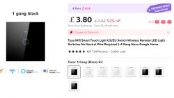
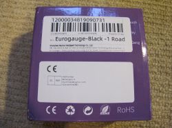
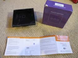
Hi. Here's a quick look at a nice easy single-gang touch sensitive switch. Going on the printed label on the box, it appears to be from Shenzhen manhe Intelligent Technology Co., Ltd.
It was from the Manhot Official Store on Ali Express https://www.aliexpress.com/item/1005005912896498.html
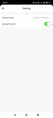
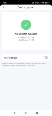
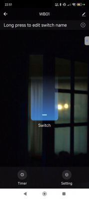
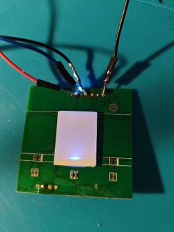
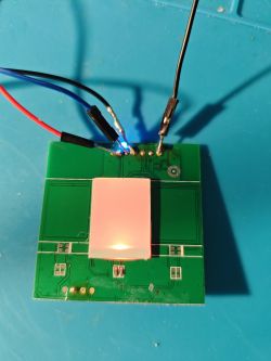
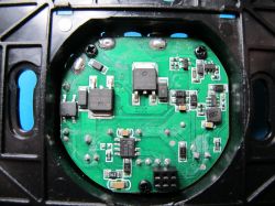
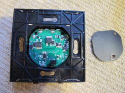
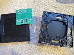
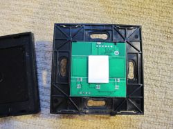
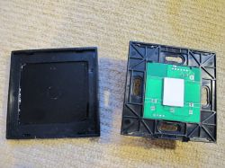
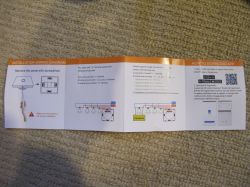
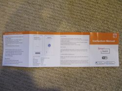
Curiously it comes with an additional MCU but I don't think the BK7231N knows about it. There are no communications I could detect with TuyaMCU Analyser and the config extraction makes no mention of one or a baud rate. tuyaMcu_sendQueryState returns no result. I think the MCU is just changing the status of the red/blue switch LED on touch panel contact which is not referenced in the extracted config. The only LED in user_params is the wifi status.
- Button (channel 1) on P24
- WiFi LED on P6
- Relay (channel 1) on P20
Possibly it would have a greater part to play depending on what these missing components are
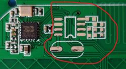
Using that product key in a search reveals a selection of similar devices, though most seem to have a CB3S module (which is also referenced in the json for this device), which this unit clearly does not have.
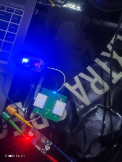
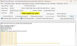
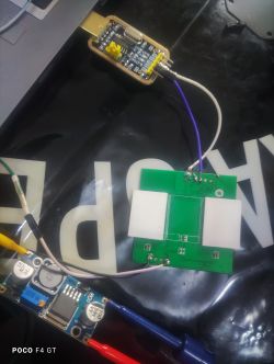
To the extent of flashing OpenBeken, these test pads were traced and UARTs used successfully
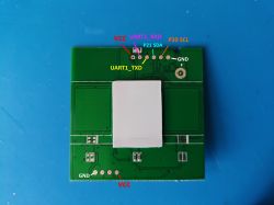
None of the test pads are UART2, so boot log was captured with a sewing needle connected directly to the UART2_TXD pin of the BK7231N, T34 stylee.
v1.3.5 known patched = no cloudcutter.
In the gang of 4 test pads at the bottom, the middle two were tested for JLink SDA connectivity but they do not appear to be so.
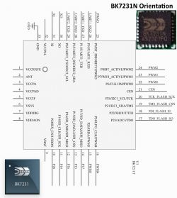
To aid me in tracing I made this to orient myself.
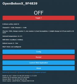
Upon flashing and import of the extracted config we have a 100% working device with behaviour like that of the factory firmware.
-button backlight and wifi LED flash when connecting to wifi and then solid blue when connected
-switch off = blue backlight hue
-switch on = red backlight hue
personally, red signals off for me, but I guess red could also be interpreted as "hot", live, on.
Template
https://github.com/OpenBekenIOT/webapp/pull/134
It was from the Manhot Official Store on Ali Express https://www.aliexpress.com/item/1005005912896498.html


Curiously it comes with an additional MCU but I don't think the BK7231N knows about it. There are no communications I could detect with TuyaMCU Analyser and the config extraction makes no mention of one or a baud rate. tuyaMcu_sendQueryState returns no result. I think the MCU is just changing the status of the red/blue switch LED on touch panel contact which is not referenced in the extracted config. The only LED in user_params is the wifi status.
- Button (channel 1) on P24
- WiFi LED on P6
- Relay (channel 1) on P20
Code: JSON
Possibly it would have a greater part to play depending on what these missing components are

Using that product key in a search reveals a selection of similar devices, though most seem to have a CB3S module (which is also referenced in the json for this device), which this unit clearly does not have.
To the extent of flashing OpenBeken, these test pads were traced and UARTs used successfully

None of the test pads are UART2, so boot log was captured with a sewing needle connected directly to the UART2_TXD pin of the BK7231N, T34 stylee.
Code: Text
v1.3.5 known patched = no cloudcutter.
In the gang of 4 test pads at the bottom, the middle two were tested for JLink SDA connectivity but they do not appear to be so.
To aid me in tracing I made this to orient myself.

Upon flashing and import of the extracted config we have a 100% working device with behaviour like that of the factory firmware.
-button backlight and wifi LED flash when connecting to wifi and then solid blue when connected
-switch off = blue backlight hue
-switch on = red backlight hue
personally, red signals off for me, but I guess red could also be interpreted as "hot", live, on.
Template
Code: JSON

https://github.com/OpenBekenIOT/webapp/pull/134


