logo elektroda
logo elektroda
X
logo elektroda

[BK7231N/CB3S] Deta Grid Connect Touchless Handwave Switch 6931HA - Teardown

terryb8s 1080 13
ADVERTISEMENT
  • #1 21206439
    terryb8s
    Level 4  
    Device Name: Deta Grid Connect Touchless Handwave Switch - 6931HA
    Device Type: LightOther switch
    Device Chip: CB3S - BK7231N
    Device Purchased: Bunnings Warehouse - $59.32NZ
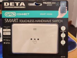
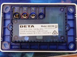
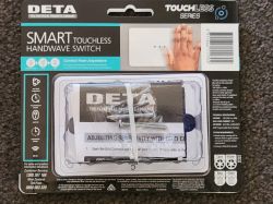
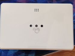
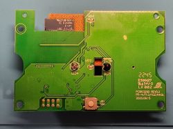
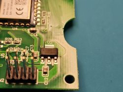
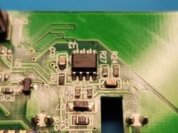
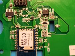
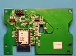
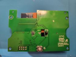
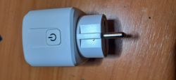
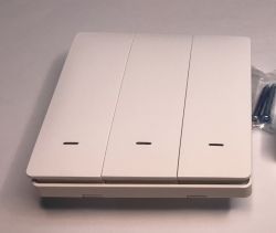
    Deta Grid Connect touchless hand switch in original packaging. Back view of the Deta Grid Connect touchless hand switch, model 6931HA, showing the terminals and technical specifications label. Packaging of the Deta Grid Connect touchless handwave switch with accessories. Touchless hand switch Deta Grid Connect with three openings and a hand icon on a white casing. Front view of the circuit board of the Deta Grid Connect touchless hand switch with LED markings. Close-up of a PCB with visible pins and electronic components. Image of a circuit board of a Deta Grid Connect touchless hand switch. Close-up of a circuit board with a CB3S module and electronic components. Close-up of the PCB of the Deta Grid Connect contactless hand switch. Close-up of an electronic board with labeled components, including two LEDs and a mounting hole.

    Flash Pins
    Pin16 - TXD1
    Pin15 - RXD1
    Pin8 - VCC (3.3V)
    Pin9 - GND

    Config
    To be determined.

    Firmware Dump
    Attached is stock firmware untouched.

    Have not been able to find anyone with a similar product so not sure how to config this as yet, be keen for any help, in the mean time going to check hardware functionality with stock firmware then flash to see what I find. It seems to have two LEDs and an infrared receive diode in center of the PCB, I imagine one of the two LEDs is infrared.
    Helpful post? Buy me a coffee.
  • ADVERTISEMENT
  • #2 21206741
    p.kaczmarek2
    Moderator Smart Home
    That's a very interesting device, but I wouldn't worry that it can be problematic to support. I think we'll manage. Most likely it has a separate circuit for wave detection and we won't have to do that on BK.

    First, you need to disassemble that and provide some detailed photos from the inside. There is no GPIO information in the flash binary, so device may be a custom one.

    How are LEDs connected? Via a separate IC?
    Helpful post? Buy me a coffee.
  • ADVERTISEMENT
  • #3 21210521
    terryb8s
    Level 4  
    Have added the photos of the PCB, it's certainly an interesting circuit, I have traced most of it out and will see about uploading a diagram of some kind but it looks like the only other larger chipIC is a LM358D which to me (with little knowledge of dual channel op amps) doesn't seem like it's what's doing the hand wave control maybe just helping? I may well be wrong though.

    I'm more wondering if it's even more simple than that... wondering if the Infrared receiver is just being detected for blocking of light vice versa for a period of time, the button on the other side of the board is used for pairing but also sensitivity (using timing thresholds?) when using it on stock firmware, it has low (default), medium and high sensitivity settings.
    Helpful post? Buy me a coffee.
  • ADVERTISEMENT
  • #4 21210534
    p.kaczmarek2
    Moderator Smart Home
    Are you able to desolder CB3S so we can get a better view of traces?

    I wonder if ADC (P23) is somehow used there. If not, maybe they use PWM...
    Helpful post? Buy me a coffee.
  • #5 21210981
    terryb8s
    Level 4  
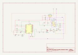
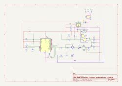
    Took me a bit but hopefully this helps, apologies if I got any components orientation incorrect its likely because I didn't trace trace this out while powered on.

    I believe I have all the connections are correct, double checked, hopefully no mistakes.

    Electrical schematic of the Deta Grid Connect touchless switch.
    Helpful post? Buy me a coffee.
  • #6 21215742
    terryb8s
    Level 4  
    >>21210981
    OK I got some of this wrong but will update when I get a chance.

    You seem to be right about PWM, P24 seems to be PWM for transmit IR LED and P14 is the input for rec IR LED, relay is on P6 along with LED2, in the diagram currently I have the LED2 on P7 which is wrong and it also looks like it's going to ground? but unsure as yet, will pull it back to bits and retrace.

    But can get the relay to trigger knowing this all this and setting P14 to a dinput, putting my hand in front of it triggers the relay on for a moment (P6 and P14 on same channel, P24 PWM_n)

    Adjusting the PWM seems to make it more or less sensitive but hard to tell at the moment as hand in front is very intermittent as to when it triggers.
    Helpful post? Buy me a coffee.
  • #8 21216706
    p.kaczmarek2
    Moderator Smart Home
    Are you sure about Q3 placement? It doesn't look right.

    Still, we can make some tests without having a perfect schematic. Just fire the PWM and try to observe what happens on another pin. Just.... we need to know which pin is PWM control (sensitivity) and which is input.

    Or maybe you'd prefer hooking up analyzer to original device with factory firmware?
    Helpful post? Buy me a coffee.
  • ADVERTISEMENT
  • #9 21217049
    terryb8s
    Level 4  
    Hmm I am tempted to get a logic analyzer or scope but not sure what to buy really, I'm still pretty new to this level of electronics reverse engineering, as you obviously can tell with my Q3 orientation (corrected the diagram above, first time using kicad as well, electronics wise I'm pretty good with a soldering iron but I'm no electrical engineer as yet as much as I pretend to be :-P

    PWM control appears to be on P24, input seems to be P14 and relay P6, playing around with the PWM slider between 25% and 35% is the most responsive, I can trigger it with my hand between as low as 20% and as high as 45% but its very hit and miss a lot of the time with those settings, anything below or above those values only works if I use something shiny 30% seems like its about the best but possibly could do with some tweaking .

    Have put P14 and P6 on the same channel and I can hear the relay open and close when I wave my hand near, so good progress.

    Pins:
    P6 Relay
    P8 WifiLED_n
    P14 dinput
    P24 PWM
    P26 Button (SW1)

    If you think its a good idea for me to get some analyzer equipment I'd be keen to know what would be best to take a look at buying.

    I'll keep playing around in the mean time, feel like I need to do some autoexec scripting and it might almost work properly.
    Helpful post? Buy me a coffee.
  • #10 21227267
    terryb8s
    Level 4  
    Got myself a scope to start getting into a bit more of the nitty gritty, still very much learning... but have some findings.

    On stock FW, it looks like the PWM frequency on P24 is closer to 2.25267khz with the PWM +duty always set to about 49.5%~ but spikes all the time to about 50%, the readings on the stock firmware seem very unstable when compared to OBK with similar settings.

    Have set the following on OBK and they seem to result in similar scope readings but a lot more stable... nowhere near the same fluctuations.

    PWMFrequency 2252.267
    SetChannelFloat 20 49.582
    (20 is the current channel for PWM)

    Are the fluctuations on stock potentially just something weird with the firmware or do you think they are doing something more specific with the PWM signal? I don't know enough about PWM to guess but will keep researching.

    Hand waving in front of the device results in repeated sine wave type spikes on the scope display for P14, this is with both stock and OBK.

    I saved some screenshots on the scope, haven't yet figured out how to get them off it as yet but can post them when I do if you think they will help?

    In the meantime I think I'm gonna proceed to start scripting the hand wave capture and triggering the relay, I'm now thinking the sensitivity setting set with the button P26 (low med high options in stock fw) for it must be scripted based on P14 and its value as changing the setting on stock doesn't seem to affect P24's PWM duty in any noticeable way. if you have any script ideas that might work for this I would appreciate the help.
    Helpful post? Buy me a coffee.
  • #11 21229883
    p.kaczmarek2
    Moderator Smart Home
    Just a random idea for now - did you measure OBK PWM with PowerSave 1? Maybe it's just not stable due to original firmware using PowerSave.... but again, it's just a wild guess.


    terryb8s wrote:
    the sensitivity setting set with the button P26 (low med high options in stock fw) for it must be scripted based on P14 and its value as changing the setting on stock doesn't seem to affect P24's PWM duty in any noticeable way. if you have any script ideas that might work for this I would appreciate the help.

    P14 seems to be just a digital input. If you are sure that PWM does not change, it could mean that maybe P14 is sampled like 100 times per second and they maybe, somehow check the amount of high states, etc? Number are for just for example, but you know what I mean? For high sensitivity, just a group of 25 high states triggers, but for mid, you need at least 50, and for low, you need at least 75... etc etc.
    Custom drivers tutorial for OBK:
    https://www.elektroda.com/rtvforum/topic4056286.html
    So, you would basically need to read digital IO on quick tick (not on every second).
    We have already something like that here:
    https://github.com/openshwprojects/OpenBK7231T_App/blob/main/src/driver/drv_adcSmoother.c
    but that one is for ADC, so you would need to replace ADC call with:
    Code: C / C++
    Log in, to see the code

    Maybe keep the moving window (ring buffer) of 100 samples, define a sampling interval, and check when the amount of high samples exceeds given threshold.
    Helpful post? Buy me a coffee.
  • #12 21413517
    darmok
    Level 2  
    Hello,
    I have found my way here in my research for the 6931HA Touchless switch. With a little mucking around, I managed to get a working ESPHOME yaml together for it. Hope it helps - here goes..
    esphome:
    name: "light-switch"
    friendly_name: Light Switch

    bk72xx:
    board: generic-bk7231n-qfn32-tuya

    # Enable logging
    logger:
    level: DEBUG

    web_server:

    captive_portal:

    mdns:

    # Enable Home Assistant API
    api:
    encryption:
    key: "*************************YourKey"

    ota:
    - platform: esphome
    password: ""

    wifi:
    networks:
    - ssid: !secret wifi_ssid
    password: !secret wifi_password
    power_save_mode: none

    text_sensor:
    - platform: libretiny
    version:
    name: LibreTiny Version

    binary_sensor:
    - platform: gpio
    id: binary_switch_1
    pin:
    number: P26
    inverted: true
    mode: INPUT
    on_press:
    then:
    - switch.toggle: switch_1

    switch:
    - platform: gpio
    id: switch_1
    name: Relay 1
    pin: P6

    status_led:
    pin:
    number: P8
    inverted: false
  • #13 21413831
    terryb8s
    Level 4  
    Hmm that's super simple compared to what I have observed, initially I tried something similar to this with my one and OBK, but had very little success with the device, to get it even close to stock it required a few more changes, I have had it working somewhat but not reliably enough to use it, in the end I opted to just buy a touch switch similar to one I already have in the rest of the house.

    Can you confirm which version you have, what I found out later on was that there are two versions of this device.

    I think this version likely uses a very different mechanism for sensing a handwave, does your one look similar?
    https://detaelectrical.com.au/product/deta-grid-connect-smart-touchless-handwave-switch/

    This is the version I have, https://grid-connect.com.au/download/6931ha/

    Are you able to post any photos of your unit and its internals?
    Helpful post? Buy me a coffee.
  • #14 21414940
    darmok
    Level 2  
    Hi,
    My unit is the latter one with the three "leds" protruding through the cover. I have attached two photos of the outer, however as it is now installed, I am reluctant to proceed with a disassembly. I used ltchiptool to analyse the unit and it returned the same results as here: UPKESPHome
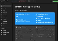
    I compared the data and yaml with another Deta switch I have and came up with the yaml posted.
    If you have the other version of the switch I would be interested to see the UPK data, maybe I just got lucky :)  

Topic summary

The discussion centers on the teardown and reverse engineering of the Deta Grid Connect Touchless Handwave Switch model 6931HA, which uses the BK7231N (CB3S) chip. The device was purchased from Bunnings Warehouse for NZ$59.32. Initial analysis suggests the handwave detection is likely handled by a separate circuit, possibly involving an infrared (IR) LED and receiver, with an LM358D op-amp present but not clearly responsible for sensing. The author traced PCB connections and identified key pins: P24 as PWM output controlling IR LED sensitivity, P14 as digital input from the IR receiver, and P6 controlling the relay. PWM frequency was measured around 2.25 kHz with duty cycle near 49.5%, showing instability on stock firmware but more stable on OpenBK (OBK) firmware. Hand waving causes sine wave-like spikes on P14 input. Sensitivity adjustments appear to be managed by PWM duty cycle changes. The relay and LEDs are controlled via GPIO pins, with some uncertainty about exact LED wiring. Attempts to replicate functionality with ESPHome and OBK firmware showed partial success but reliability issues, possibly due to two different hardware versions of the device. The discussion includes schematic diagrams, photos, and firmware dumps. Suggestions include using logic analyzers or oscilloscopes for further signal analysis and exploring custom firmware drivers to handle digital input sampling for handwave detection. The community shared ESPHome YAML configurations for a similar device version, highlighting differences in hardware and firmware behavior.
Summary generated by the language model.
ADVERTISEMENT