This is a short teardown of the DETA Grid Connect Smart Inline Switch (6000HA). It is sold in Australia and costs approximately $30 AUD from Bunnings.
The switch uses a WB2S (BK7231T) Tuya chip. This device is slightly more difficult to flash compared to other Deta branded products, insofar as that there are fewer accessible GPIO pins from the daughter board, and as such, Rx (Pin 11) is used for the onboard button. As such, it is attached to (what I assume is) the associated debouncing circuitry, which doesn't play nice with UART. As such, you'll need to break the solder connection between Pin 11 and the main board - more on that in a moment.
Getting to the PCB
First, remove the two end covers by unscrewing them.

Pry off the case by using a prytool or your nails to pull out the short edge, then lift straight up.
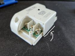
Pull out the PCB by lifting it straight up. It is not screwed in.
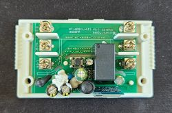
Installing OpenBK7231T
You'll need to solder jumper wires to the WB2S chip. There are contacts on both sides of the chip.
With the label facing you, connect a wire to the leftmost contact - CEN:
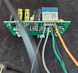
Now, on the reverse side, connect wires to the 4 left contacts:
1. 3.3V
2. Gnd
3. RX1 (Pin 10)
4. TX1 (Pin 11)
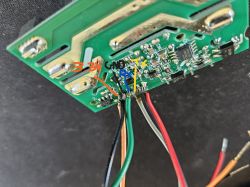
NOTE: You'll need to use some solder wick or similar to remove the solder from the joint of TX1 (4th contact on the back of the WB2S), to disconnect it from the main board electrically. Failure to do so will result in serial communication failing, and thus being unable to flash the device.
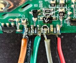
Connect these wires to your flashing device accordingly (I am using a Raspberry Pi). Leave the CEN wire hanging loose - this is used to reset the chip when ready to flash, by connecting it to Gnd momentarily.
It is recommended to use an external 3.3V regulator + power supply (such as an AM1117), as most USB serial devices and Raspberry Pis cannot supply the current required to flash the Tuya chips.
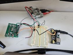
You may have to reset the chip and/or attempt flashing a few times before the chip is recognised.
Web App Configuration:
The chip started up fine with no issues. I configured WiFi and added the pin configuration below, obtained through some educated guesses + trial and error.
- P6: WifiLED_n
- P11: Btn 1
- P26: Relay 1
JSON template:
The switch uses a WB2S (BK7231T) Tuya chip. This device is slightly more difficult to flash compared to other Deta branded products, insofar as that there are fewer accessible GPIO pins from the daughter board, and as such, Rx (Pin 11) is used for the onboard button. As such, it is attached to (what I assume is) the associated debouncing circuitry, which doesn't play nice with UART. As such, you'll need to break the solder connection between Pin 11 and the main board - more on that in a moment.
Getting to the PCB
First, remove the two end covers by unscrewing them.

Pry off the case by using a prytool or your nails to pull out the short edge, then lift straight up.

Pull out the PCB by lifting it straight up. It is not screwed in.

Installing OpenBK7231T
You'll need to solder jumper wires to the WB2S chip. There are contacts on both sides of the chip.
With the label facing you, connect a wire to the leftmost contact - CEN:

Now, on the reverse side, connect wires to the 4 left contacts:
1. 3.3V
2. Gnd
3. RX1 (Pin 10)
4. TX1 (Pin 11)

NOTE: You'll need to use some solder wick or similar to remove the solder from the joint of TX1 (4th contact on the back of the WB2S), to disconnect it from the main board electrically. Failure to do so will result in serial communication failing, and thus being unable to flash the device.

Connect these wires to your flashing device accordingly (I am using a Raspberry Pi). Leave the CEN wire hanging loose - this is used to reset the chip when ready to flash, by connecting it to Gnd momentarily.
It is recommended to use an external 3.3V regulator + power supply (such as an AM1117), as most USB serial devices and Raspberry Pis cannot supply the current required to flash the Tuya chips.

You may have to reset the chip and/or attempt flashing a few times before the chip is recognised.
Web App Configuration:
The chip started up fine with no issues. I configured WiFi and added the pin configuration below, obtained through some educated guesses + trial and error.
- P6: WifiLED_n
- P11: Btn 1
- P26: Relay 1
JSON template:
Code: JSON


